Calidus
SYSTEM DESCRIPTION
AutoGyro_POH_Calidus Revision 4.0 – Issue Date 17.JAN.2019 7-14
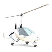
View of strap limit stop stops fitted – comprise 2 washers, screw and nylock nut per strap.
Rudder and front wheel control
The Rudder is connected to the foot pedals with steel cables which are routed horizontally
along the main frame. Both pairs of pedals are interconnected by a linkage. The nose wheel
steering is directly linked to pedal/rudder control input by control rods. The rear pedals are
an option fit item for instructional use.
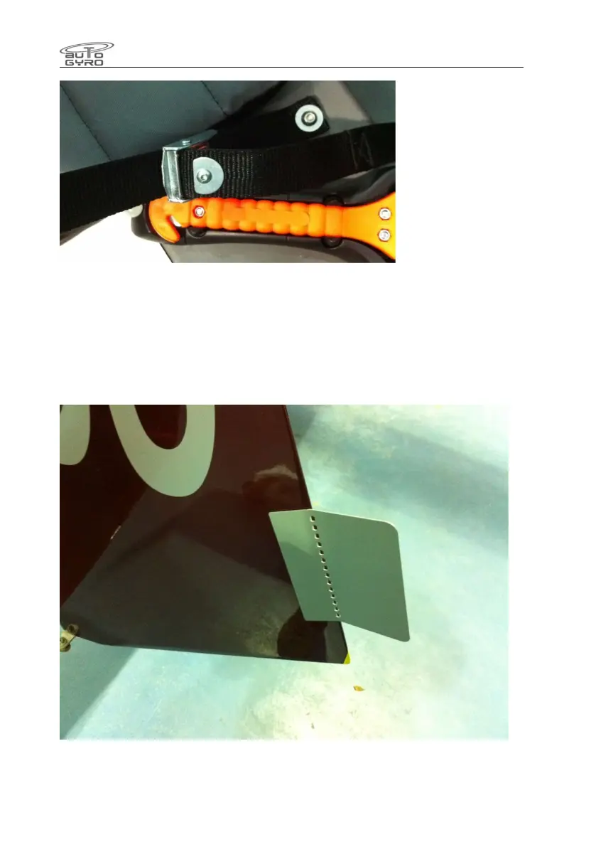
The rudder is fitted with a trim tab.
This is normally biased to the left, and may be adjusted by the operator to trim the aircraft
for straight flight at a desired speed, feet off the pedals. Adjusting it to the left will biase the
rudder to the right and vice versa.
 Loading...