Calidus
SYSTEM DESCRIPTION
AutoGyro_POH_Calidus Revision 4.0 – Issue Date 17.JAN.2019 7-24
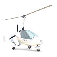
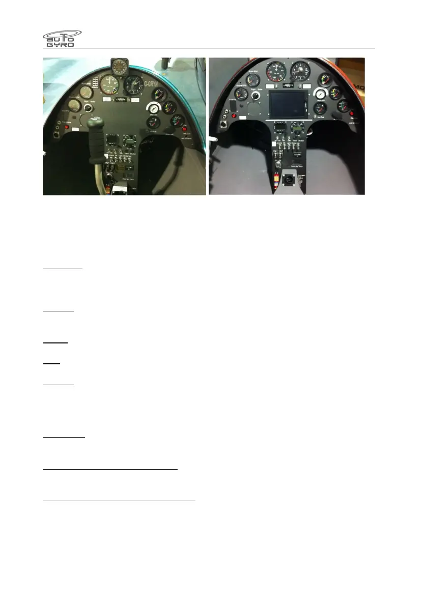
Photographs of early instrument panels showing the warning lamps located centrally.
Equipment function is the same as later generation panels.
Switch functions
Keyswitch. First stop supplies power to the instrument panel and equipment. Second stop
will engage starter motor. An interlock prevents re engagement of the starter without cycling
the switch to ‘off’ first.
Avionics. On supplies power to the radio, transponder and GPS (where fitted). Also the
electronic ASI and Altimeter (where fitted)
Lights. On supplies power to the landing lights (where fitted)
Nav. On supplies power to the navigation lights (where fitted)
Strobes. On supplies power to the strobe lights (where fitted)
Mag switches. When off this earths the cable to the engine ignition coils, preventing engine
start.
Fan button. With the keyswitch on, depressing this will start the engine cooling fan. The fan
will run for a set period and then stop automatically. The fan motor draws 8A.
Change over switch (Brake to Flight). Changes the air supply to the trim/brake cylinder to
either allow the rotor brake or the in-flight pitch trim to be applied.
Pre-rotator & rotor brake interlock release. Depressing this button with the rotor brake
applied will allow the use of the pre rotator to drive the rotors to a centered position.