Automatic Systems Logic D1 v06-02-en0802.doc ERB-PM Technical manual
20/31
C.
CONFIGURATION
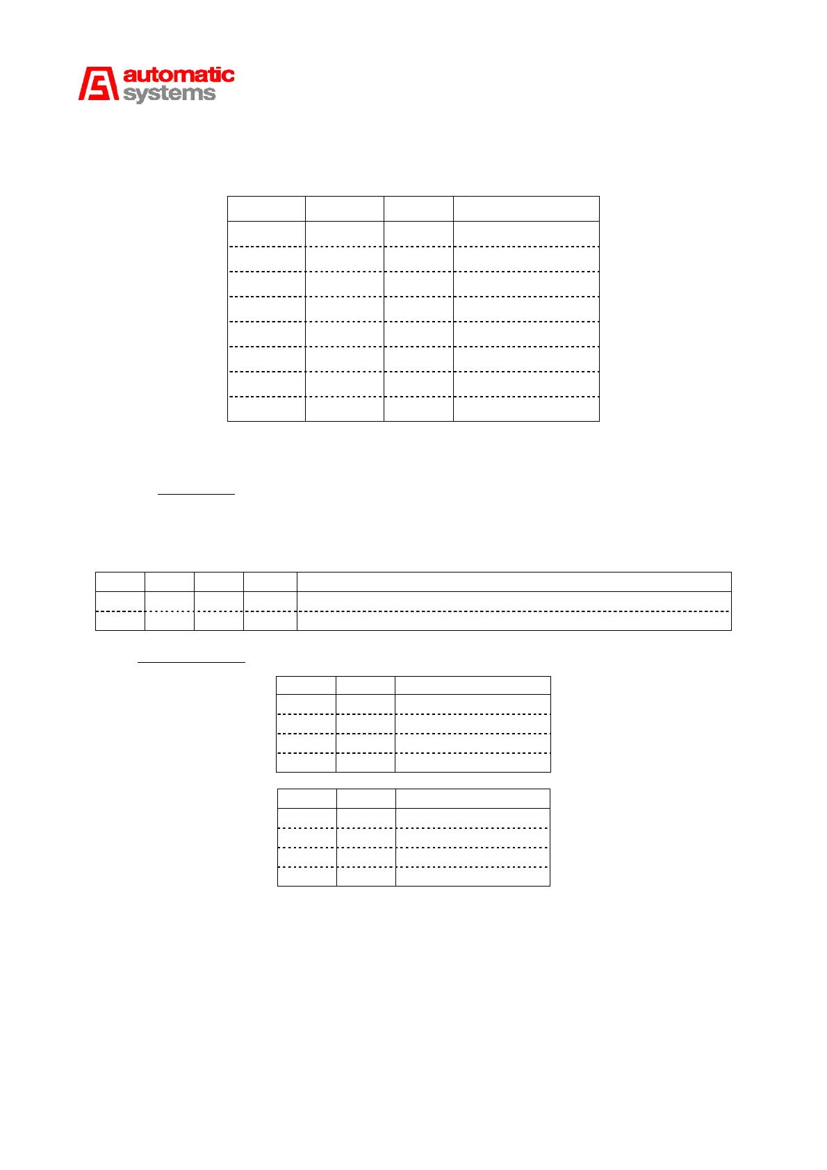
The switches SW1 (6:5) of detector 1 and SW4 (6:6) of detector 2 (on the DP239 board)
configure one or both sensors to DP functions according to the table below.
DIP 1 DIP 2 DIP 3 Functions
OFF OFF OFF Inactive
ON OFF OFF DPO
OFF ON OFF Not allocated
ON ON OFF DPFS-S-F
OFF OFF ON DPFS-O-F
ON OFF ON DPS-S
OFF ON ON DPS-O
ON ON ON DPI
The switch SW3 (6:7) configures the I²C address, the sensitivity and the frequency of the loops.
I²C Address: When one or two cards are installed on connectors X3 and/or X4, it is important to
be able to recognise them and differentiate them when programming the sensors.
The Low address corresponds to sensors 1 and 2 (function DP1-DP2).
The High address corresponds to sensors 3 and 4 (function DP3-DP4).
The first 4 DIP of SW3 (6:7) determine the selection of addresses:
DIP 1 DIP 2 DIP 3 DIP 4 Address
OFF OFF OFF OFF DP1 (board DP139) or DP1 and DP2 (board DP239) – Low Address
ON OFF OFF OFF DP3 (board DP139) or DP3 and DP4 (board DP239) – High Address
Sensitivity setting
DIP 5 DIP 6 Sensitivity of loop 1
OFF OFF High
OFF ON Medium high
ON OFF Medium low
ON ON Low
DIP 7 DIP8 Sensitivity of loop 2
OFF OFF High
OFF ON Medium high
ON OFF Medium low
ON ON Low