Automatic Systems Logic D1 v06-02-en0802.doc ERB-PM Technical manual
21/31
Frequency setting
DIP 9 DIP 10 Frequency
OFF OFF High
OFF ON Medium high
ON OFF Medium low
ON ON Low
Note: After each modification on the DP board setting, it is necessary to reset the logic by
switching-off the main power supply during 1 second.
2.5.5.4. The board AS1225
The board AS1225 manage the input of one or two external dry contacts connected instead of the
loops in the same way as the detectors (DPI, DPO, DPFS, DPS).
For example: the contact from an external detector or from a photocell.
The AS1225 are connected to connectors X3 (1:3) or/and X4 (1:4) of the AS1200.
A. CONNECTIONS
The functions and connection of the external contacts depend on the address allocated to each
board according to the table of various addresses in § 2.5.5.1. Sensor Boards.
Contact 1 of the board placed on connector X3 (1:3) has to be connected on terminals X7↑ 21
and 22 in and contact 2 to terminals X7↑ 19 and 20.
Contact 3 of the board placed on connector X4 (1:4) has to be connected on terminals X7↓ 43
and 44 and contact 4 on terminals X7↓ 41 and 43.
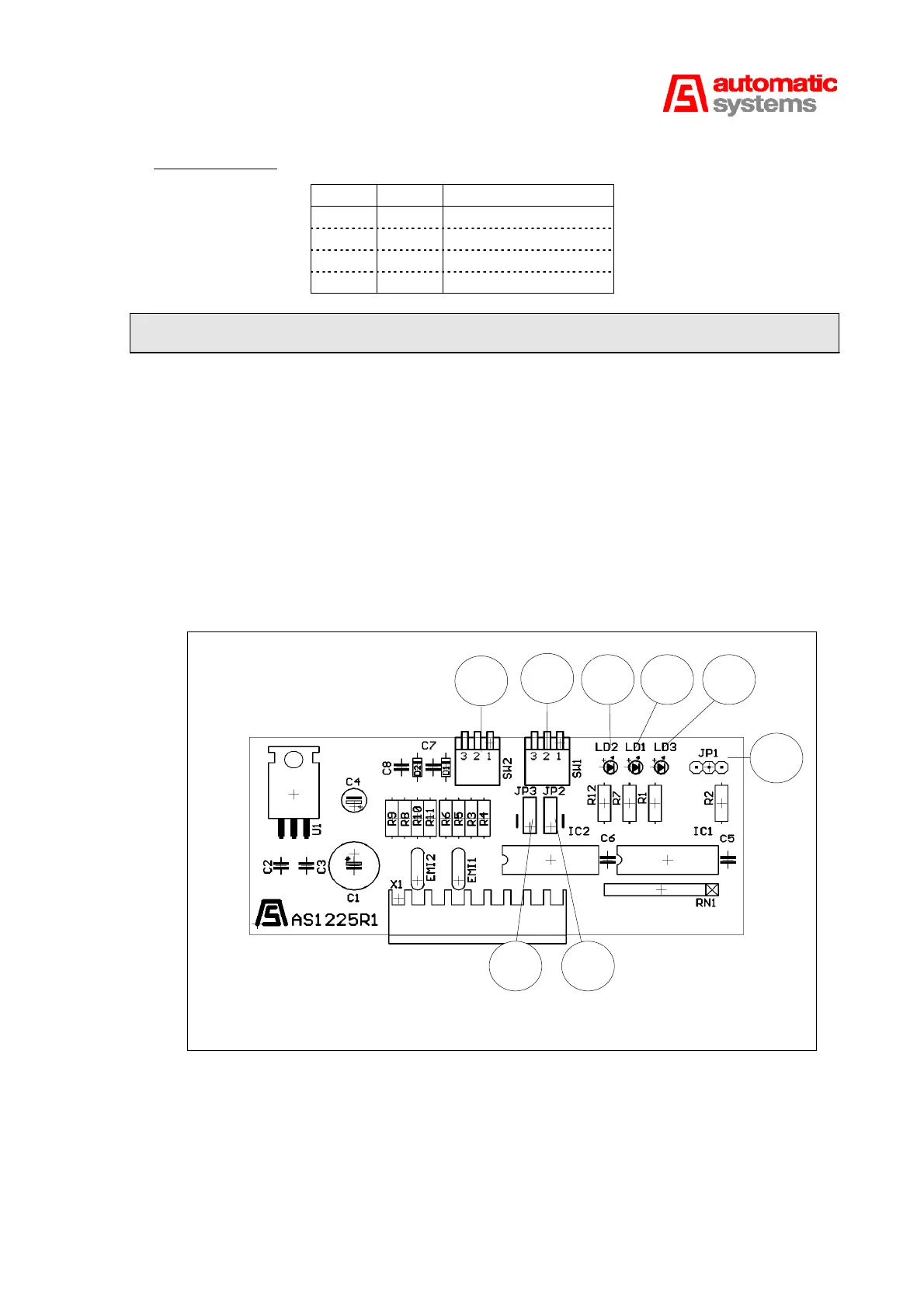
B. INDICATIONS
The LED LD3 (7:6) shows whether the board is on power.
The lit LED LD1 (7:7) indicates that the entry 1 is activated.
The lit LED LD2 (7:8) indicates that the entry 2 is activated.
Activation of one input corresponds to the closing of the NO contact or opening of the NC contact.
Fig. 7
7:1
7:2
7:3
7:67:77:8
7:47:5