Automatic Systems Logic D1 v06-02-en0802.doc ERB-PM Technical manual
27/31
4.
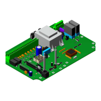
The Board AS1206
The AS1206 is necessary for a three-phase configuration.
The main three-phase power supply is to be wired on the connector X1 (9:1). The terminals N and L (9:2)
send the single-phase power supply back to connector X1 (1:1) of the board AS1200.
The wires soldered on X2 (9:3) for the command of the contactor (24V DC) are plugged on the connector X9
(1:9) of the board AS1200.
X3 (9:4) is the connector of the three-phase motor. The terminal PE is connected to the earth. The terminals
U, V and W correspond to the three phases. The terminals C1 and C2 are the common points of the star
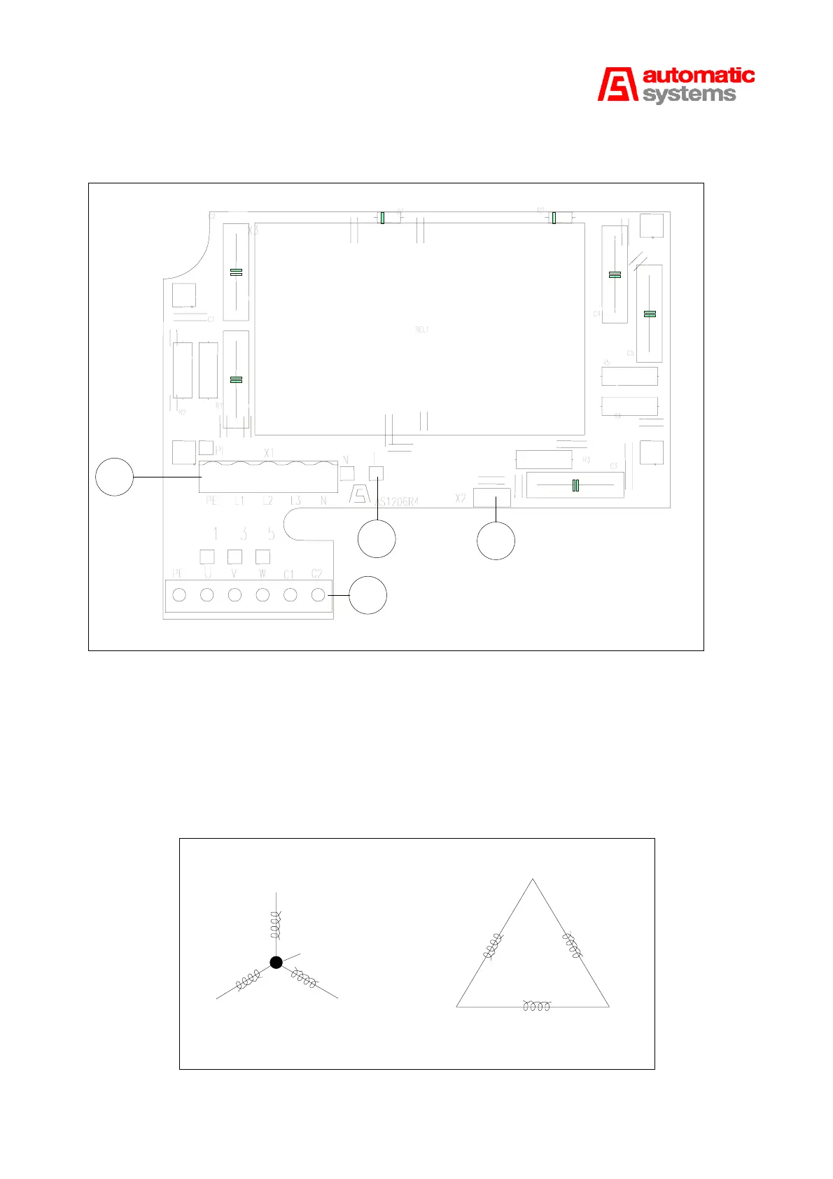
wiring (see Fig. 10).
Motor connection
U
V
W
C1-2
U
V
W
400V configuration
230V configuration
Fig. 10
STAR
TRIANGLE
9:1
9:2
9:3
9:4
Fig. 9