Automatic Systems Logic D1 v06-02-en0802.doc ERB-PM Technical manual
23/31
3.
The Interface Board AS1220
3.1.
Overview
The board AS1220 can manage peripherals linked to the barrier such as the electromagnetic tip support, the
electromechanical tip support and the lights on the boom.
It also controls the passage traffic lights (red and green associated to the movements of the barrier) or a
flashing (or revolving) light or information copy-outs on relays (see §2.4.1. Parameters), or the control of a
slave barrier, by means of relays REL1 (8:5) and REL2 (8:6).
The AS1220 is linked to the board AS1200 with one of the connectors X5 or X6.
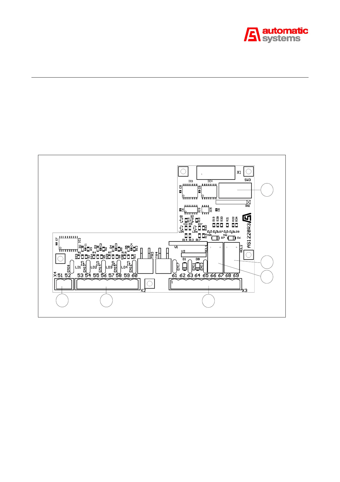
The selection of functions for the peripherals are defined by the 8 DIP of the switch SW3 (8:4).
8:3 8:1 8:2
8:4
8:6
8:5
Fig. 8
The board has four inputs on the connector X2 (8:1) and 5 outputs on the connector X3 (8:2) including one
power output 24V DC 150 mA maxi from the AS1200, two outputs 24V DC (transistor) and two relay NO
contacts.
The connector X4 (8:3) is the input of the 24 VDC power supply from the AS1048 board and not by the
AS1200 board.