Automatic Systems Logic D1 v06-02-en0802.doc ERB-PM Technical manual
30/31
6.
The Board AS1049
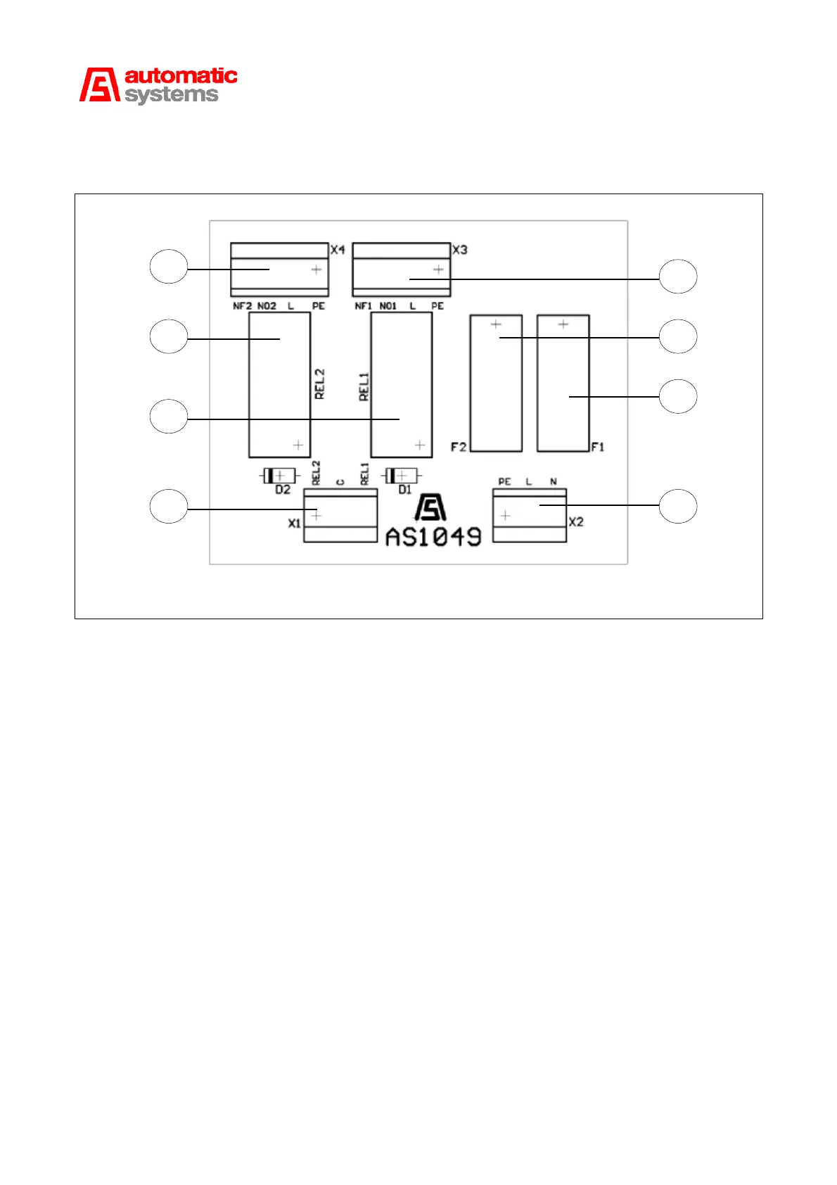
Fig. 12
The AS1049 board is used to double the command relays for the AS1200 and AS1220 boards during use of
one or two obstacle passage traffic lights.
It will be connected to the AS1220 board to make it possible to define the passage direction with two lights.
F1 (12:3) Protection fuse of line N that passes through the common contacts of relays REL1 and REL2.
F2 (12:2) Protection fuse of line L that supplies common power to the bulbs.
REL1 (12:6) is the command relay for the light defined on entry.
REL2 (12:7) is the command relay for the light defined on exit.
CONNECTIONS
X1 (12:5) Input connector for the command signals for REL1 and REL2, coming from the NO contacts of
the boards AS1200 or AS1220.
Terminal X1: 1: for REL2, terminal X1: 2: for the common part and terminal X1:3: for REL1.
X2 (12:4) Single-phase supply connector.
PE: Earth. L: Live N: Neutral
X3 (12:1) Outputs connector for the contacts from relay REL1 which is used to connect the green bulb
(authorisation) in case of a single traffic light or to connect the red-green light defined on
entry in the case of two lights.
X4 (12:8) Outputs connector for the contacts from relay REL2 which is used to connect the red bulb
(prohibition) in the case of a single light and to connect the red-green light defined on exit
in the case of two lights.
12:3
12:2
12:4
12:5
12:1
12:6
12:7
12:8