Automatic Systems Logic D1 v06-02-en0802.doc ERB-PM Technical manual
29/31
5.
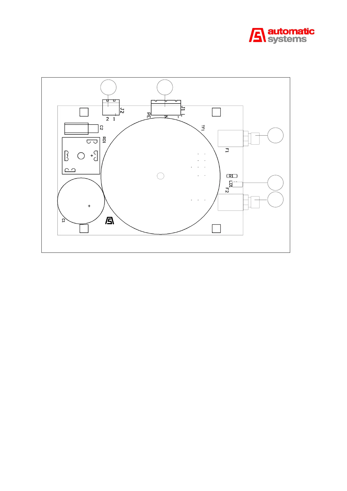
The Board AS1048
The AS1048 board provides the power supply 24 VDC to the board AS1220 for the boom lighting, the
electromechanical rod (on some barrier models) and the electromagnetic or electromechanical tip supports.
J1 (11:1) is the input single-phase 230V connector.
J2 (11:2) is the 24 V DC output connector:
Pin 1: Ground and Pin 2: +24 V.
The board comprises a fuse F1 T100 mA (11:3) and a fuse F2 T3.15 A (11:4).
The red LED (11:5) indicates that power is on.
11:2
11:1
11:3
11:4
11:5
Fig. 11