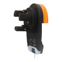
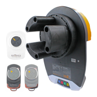
GDO-12 HIRO Installation Manual
20
A - Adjustment Mode Parameters
10. Appendix
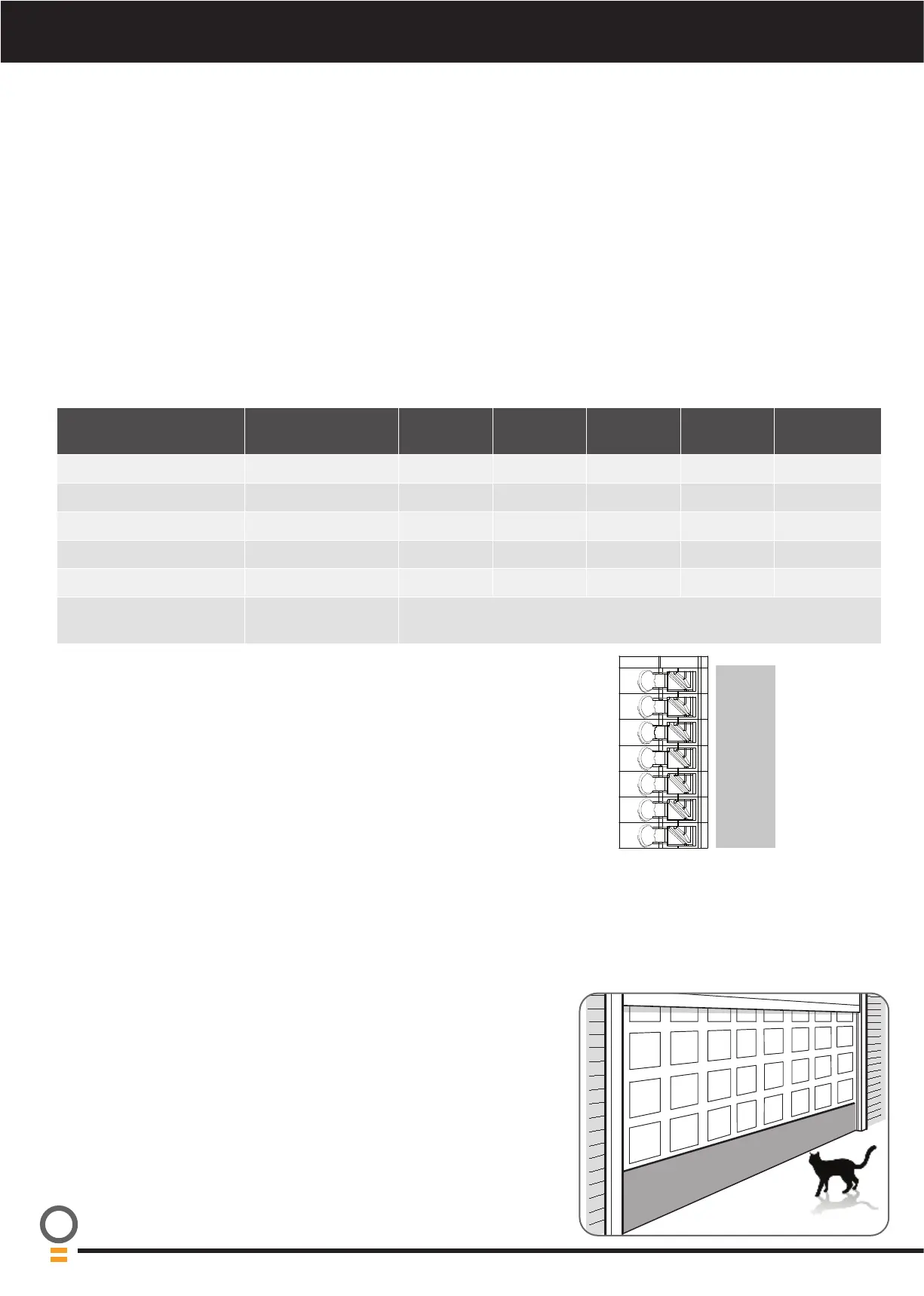
LED Indicators Parameter OPEN OPEN &
STOP
STOP CLOSE &
STOP
CLOSE
LAMP LED Light Time 180s 120s 60s 30s 0s
AUX LED Aux Time / Mode Toggle 60s 30s 1s Mimic Light
A/C LED A/C Function 90s 60s 30s 15s OFF
A/C & BEAM LED’S P.E A/C Function 60s 30s 15s 5s OFF
OBST LED Margin Setting 20 units 15 units 12 units 9 units 7 units
OPEN / STOP / CLOSE
LED’S
PG3 custom setting When all three lights are illuminated a custom setting is in place.
Parameters can be still adjusted to those listed above.
Adjustment Mode
Adjustments can be made to functions such as Light times, Auto Close functions etc. The below table shows the parameters
that can be altered.
a. Press and release the MODE button until the Spanner LED (Adjustment Mode) is highlighted.
b. One of the word LED’s (LAMP, AUX, etc) will highlight.
c. Use the BLUE CLOSE or GREEN OPEN buttons to move to the particular parameter.
d. Press RED STOP / SET to enter the adjustment mode.
e. The OPEN, STOP and CLOSE LEDS will now flash and indicate the parameters value as shown in table below.
f. Use the BLUE CLOSE or GREEN OPEN buttons to adjust the parameter value by one step up or down.
g. Press RED STOP / SET to save the new value or MODE to cancel the edit - flashing will stop.
h. To enter another parameter repeat from Step a.
Appendix
When activated, PET mode drives the door to a preset position from the close
position, therefore allowing a pet or parcel to go under the door.
a. Drive and stop the door at the desired PET mode open position by
pressing the transmitter button coded for Open/Stop/Close operation.
b. Press the MODE button twice to highlight the LIMIT LED.
c. Press the BLUE CLOSE button to scroll through to highlight the PART LED.
d. Press and hold the RED STOP / SET button for 2 seconds and release.
B - Setting the PET Mode position
SB1
0V
SB2
0V
OSC
0V
AUX
Auxiliary Output
The auxiliary output can be used to control alarm or another garage door opener.
A valid transmission from the pre-coded transmitter will cause the auxiliary output
to pulse for approximately 1 (one) second. The maximum DC voltage must not
exceed 35 volts DC. Maximum current must not exceed 80 ma.