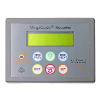
Installation Instructions MegaCode
®
Receiver 13
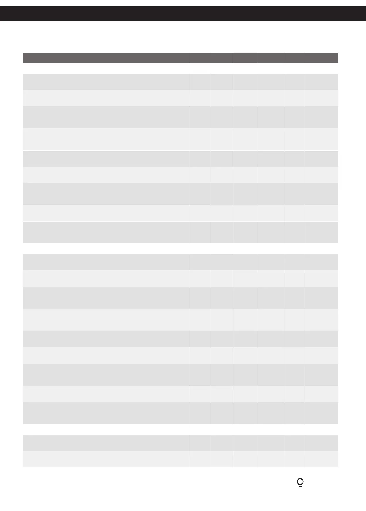
Parameter Min Max Default Unit Menu Section
Menu 4 - Output Three Setup
OUTPUT PULSE TIME: This parameter sets the duration of the output pulse
time. The output pulse time is used only for pulse functions.
0.1 99.9 1.0 Sec. 4.1 Appendix B
PULSE TIME UNITS: This parameter sets the units used for the ouput time
settings. The options are Sec, Min or Hrs.
Sec Hrs Sec Sec, Min,
Hrs
4.2 Appendix B
FLASH ON TIME: A flash on output is created by repeatedly turning the
output on and off. The Flash On time sets the duration of the on phase. For
a steady output state which does not flash, set the Flash on Time = 0.0s.
0.0 999.9 Off Sec 4.3 Appendix B
FLASH OFF TIME: A flash off output is created by repeatedly turning the
output on and off. The Flash Off time sets the duration of the off phase. The
Flash Off Time is not used for steady state outputs.
0.1 999.9 0.5 Sec 4.4 Appendix B
COMPLETE FLASH SEQUENCE: Turning this parameter on will allow the
flash cycle to complete if the output is turned off during the flash cycle.
Off On Off 4.5 Appendix B
OUTPUT THREE INVERTED: This parameter allows its operation to be
changed to N/C.
Off On Off 4.6 Appendix B
TRIGGER THREE INPUT: Output Three can also be controlled via
independent Trigger Three input. The trigger input can be programmed to
activate its output similar to a transmitter button.
Off On Off 4.7 Appendix B
TRIGGER THREE INPUT CONTACT: This parameter allows its operation to
be changed to N/C.
Off On Off 4.8 Appendix B
DISABLE THREE INPUT CONTACT: This input can be used to disable the
output in software regardless of the state of the transmitters, wired inputs or
time clock. The parameter allows it operation to be changed to N/C.
Off On Off 4.9 Appendix B
Menu 5 - Output Four Setup
OUTPUT PULSE TIME: This parameter sets the duration of the output pulse
time. The output pulse time is used only for pulse functions.
0.1 99.9 1.0 Sec. 5.1 Appendix B
PULSE TIME UNITS: This parameter sets the units used for the ouput time
settings. The options are Sec, Min or Hrs.
Sec Hrs Sec Sec, Min,
Hrs
5.2 Appendix B
FLASH ON TIME: A flash on output is created by repeatedly turning the
output on and off. The Flash On time sets the duration of the on phase. For
a steady output state which does not flash, set the Flash on Time = 0.0s.
0.0 999.9 Off Sec 5.3 Appendix B
FLASH OFF TIME: A flash off output is created by repeatedly turning the
output on and off. The Flash Off time sets the duration of the off phase. The
Flash Off Time is not used for steady state outputs.
0.1 999.9 0.5 Sec 5.4 Appendix B
COMPLETE FLASH SEQUENCE: Turning this parameter on will allow the
flash cycle to complete if the output is turned off during the flash cycle.
Off On Off 5.5 Appendix B
OUTPUT ONE INVERTED: This parameter allows its operation to be
changed to N/C.
Off On Off 5.6 Appendix B
TRIGGER FOUR INPUT: Output Four can also be controlled via independent
Trigger Four input. The trigger input can be programmed to activate its
output similar to a transmitter button.
Off On Off 5.7 Appendix B
TRIGGER FOUR INPUT CONTACT: This parameter allows its operation to
be changed to N/C.
Off On Off 5.8 Appendix B
DISABLE FOUR INPUT CONTACT: This input can be used to disable the
output in software regardless of the state of the transmitters, wired inputs or
time clock. The parameter allows it operation to be changed to N/C.
Off On Off 5.9 Appendix B
Menu 6 - Operating Modes
DEFAULT TRANSMITTER BUTTON 1: This parameter is used to set the
default output function when coding button 1 of the transmitter.
6.1 Appendix B
DEFAULT TRANSMITTER BUTTON 2: This parameter is used to set the
default output function when coding button 1 of the transmitter.
6.2 Appendix B
Appendix
A - Receiver Menu Structure