10
NeoSlider
TM
- Sliding Gate Opener NES-24V3 Owner Installation Instructions
8. Setting Limits
The NeoSlider
TM
has the alternate ability to set travel limits using a
TrioCode
TM
128 transmitter, allowing free movement around the gate to
better assess the desired limit positions. In order to use a transmitter, it
must first have at least one of its buttons coded to the gate controller.
The function assigned to the transmitter’s buttons is of no concern here
as the buttons are temporally assigned to OPEN, CLOSE and SET (Fig.
8.1).
NOTE: Gate should be moved manually to fully open position. When
re-engaging opener, nudge gate until click is heard to confirm pinion
gear has engaged fully.
8.1 Setting Travel Limits
Navigating to “code transmitter” menu
a. Press NEXT to navigate to Menu 1.
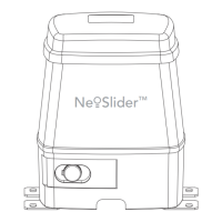
b. Press SET to enter the code set procedure (Fig. 8.2).
Storing Transmitter Code
c. Controller will prompt to press one of the transmitter’s Button.
d. Press the transmitter button you wish to use to operate the gate
opener (e.g. button 1) .
e. Press the same transmitter button again as prompted by display.
f. Press the SET button to store the transmitter.
Navigating To “Set Gate Travel Menu”
g. Press PREV to navigate to Menu 10.
h. Press SET to display MENU 10.1.
i. Press SET two times to enter the limit setting procedure. Follow LCD
prompts.
8.2 Setting the left/right installation side settings
a. Select left or right installation side by pressing open button for the
correct side (Fig. 8.2).
b. Press SET to confirm.
8.3 Setting close travel limit
a. Press and hold Button 4 on the transmitter to close the gate
i. If the gate is closed too far, press Button 1 to “inch” the gate
towards open.
ii. When happy with the close limit position, press Button 2 to store
this in the memory.
NOTE: Limit will not be accepted unless the gate is driven in the
close direction.
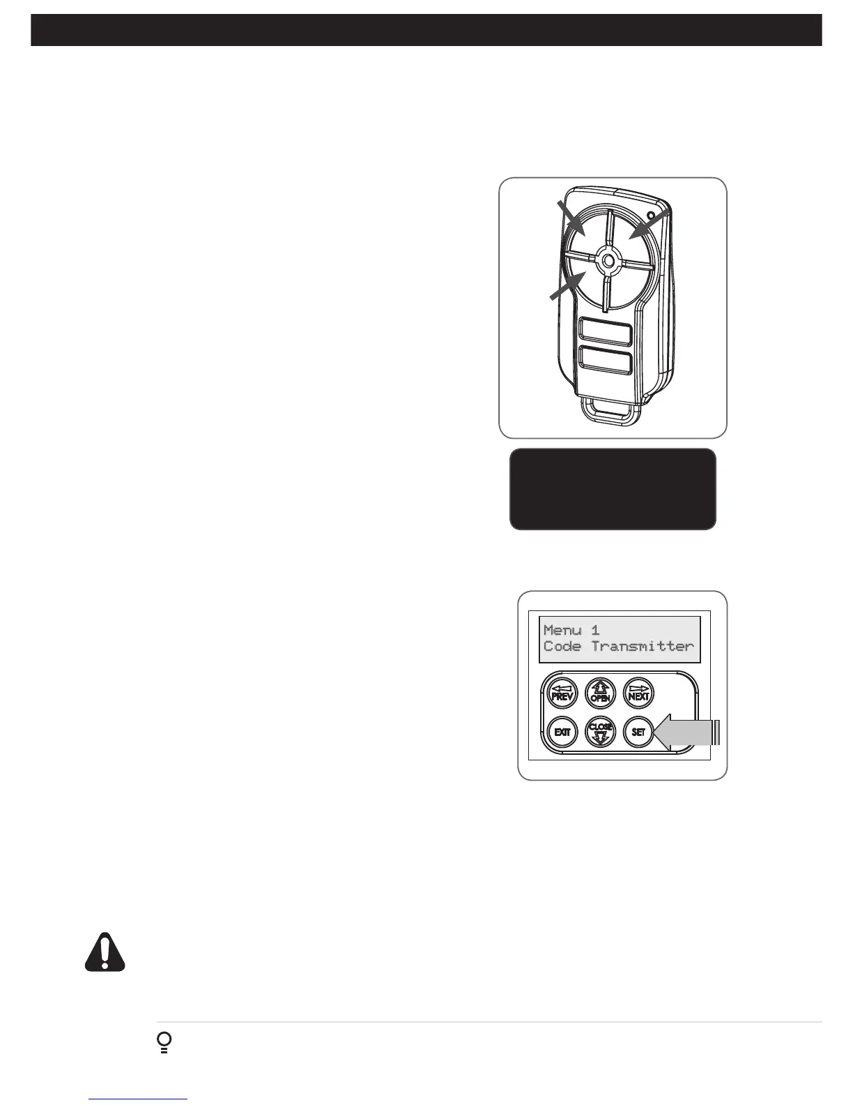
Fig 8.1
Fig 8.2
Button 1
(Inch
Open)
Button 4
(Inch
Close)
Button 2
(Set)
8.4 Setting open travel limit
a. Press Button 1 to open the gate.
b. If the gate is opened too far, press Button 4 to “inch” the gate
towards close
c. When happy with the open limit position, press Button 2 on the
transmitter to store into memory..
IMPORTANT NOTE:
Only TrioCode
TM
128 Technology
Transmitters are compatible
with this product.
NOTE: Limit will not be accepted unless the
gate is driven in the open direction.
WARNING: The gate will automatically close and open once next step is
performed. Ensure that no persons or objects are in the gates path
d. The gate will now automatically close and open to calculate the safety obstruction settings.