Owner Installation Instructions NeoSlider
TM
- Sliding Gate Opener NES-24V3 7
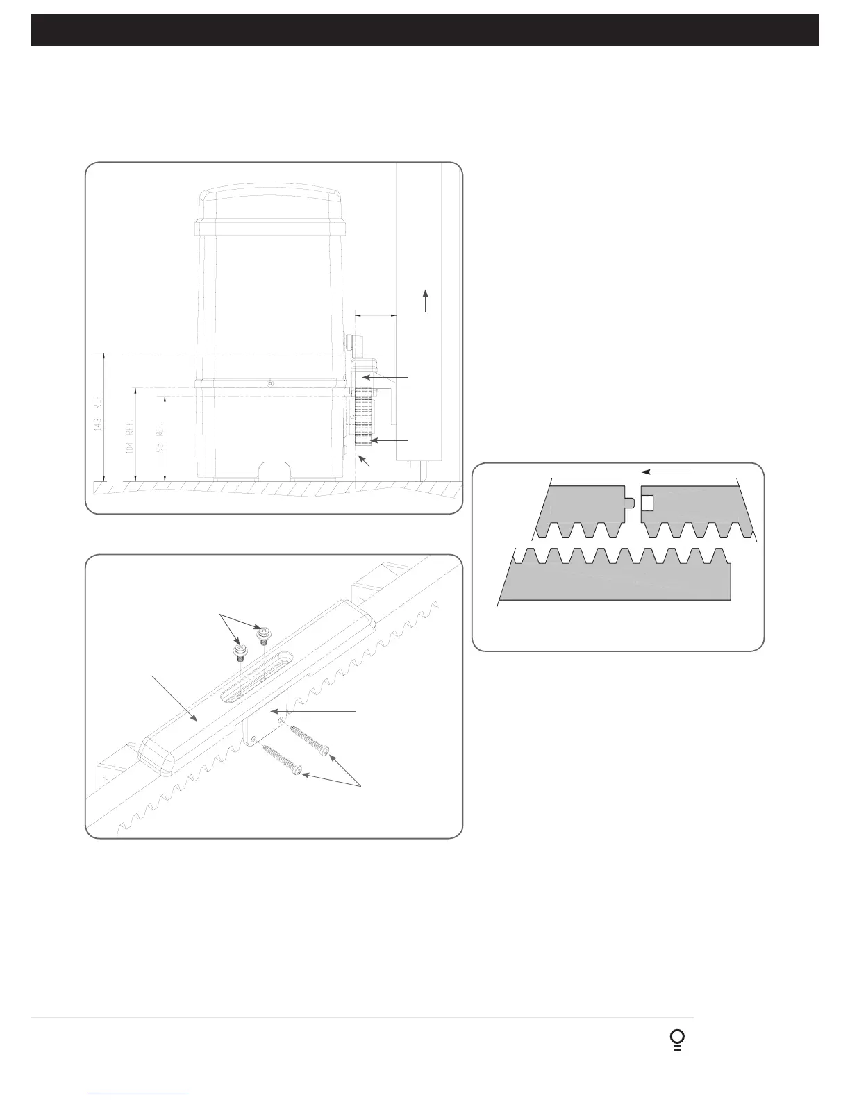
5. Rack & Limit Actuator Installation
5.1 Mounting rack to gate
A strong base on the gate is required for mounting
the rack.
a. Manually open the gate and place a rack section
to mesh with the pinion gear on the Drive Unit.
Mark the top of the rack. Move the gate and mark
the rack for the entire length of the gate.
b. Position the top edge of the rack on this line and
mark the centres of the rack’s mounting slots. The
first section of rack should start 20mm from the
edge of the gate.
c. Drill and tap for 6mm (¼”) screws.
d. Once the first section of the rack is mounted,
check that it meshes with the NeoSlider™ pinion
gear.
e. When joining subsequent sections of rack, check
the mesh by placing a spare section upside down
(teeth facing upwards) and putting it into mesh
with the racks being joined (Fig. 5.2).
Rack
width
Gate
Rack
Drive
gear
Datum line
To top of pinion
To bottom of
rack tooth
Maximum height of rack
Fig 5.1
Fig 5.2
Mounting
holes
M4 x 10 screws
and washers
Actuator mounting
block
M4 x 30 screws
Fig 5.3
5.2 Fixing limit actuator to rack
a. Manually open the gate to the open position and mark this on
the gate rack under the actuating arm.
b. Manually close the gate to the closed position and mark this on
the gate rack under the actuating arm.
c. Place start of limit actuator at marked position and move it 5 to
10mm towards the centre of the gate. Align the face of the limit
actuator with the side of the rack and screw the limit actuator to
the rack (Fig. 5.3).
f. Tighten the racks. This will ensure that the
NeoSlider™ pinion can run along the racks
without obstruction.
d. Re-check limit positions by manually opening and
closing the gate, checking to see that the limit is
activated at the desired open and close position.
If neccessary, make adjustments by sliding the
actuator in the required direction. When the final
settings are established, tighten the limit actuator
screws - each actuator must be secured with two
(2) screws.