24
NeoSlider
TM
- Sliding Gate Opener NES-24V3 Owner Installation Instructions
Appendix
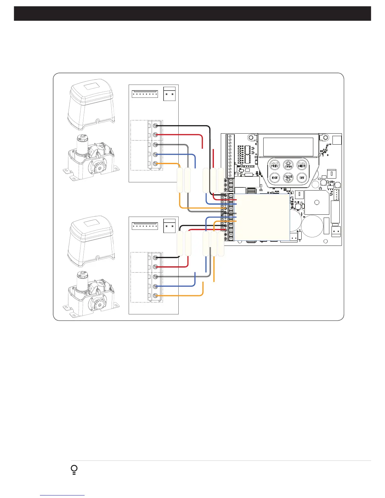
C - Wiring Dual NeoSlider Kit
MOTOR 2 TERMINAL 1
MOTOR 2 TERMINAL 2
MOTOR 2 CLOSE LIMIT SWITCH INPUT
MOTOR 2 OPEN LIMIT SWITCH INPUT
COMMON FOR MOTOR 1 & 2 LIMIT SWITCHES
MOTOR 1 CLOSE LIMIT SWITCH INPUT
MOTOR 1 OPEN LIMIT SWITCH INPUT
MOTOR 1 TERMINAL 1
MOTOR 1 TERMINAL 2
V PWR FOR ACCESSORIES
OV
Limits Motor
C O
Com
1
2
MSI-1.00 Board
Limits Motor
C O
Com
1
2
MSI-1.00 Board
ATA DCB-05V2 (150VA)
Red
Black
White
Blue
Orange
Black
White
Orange
Red
Blue
Fig C.1
This section illustrates how to wire two NeoSlider slave units into a DCB-05V3. (Fig. C.1)
NOTE:
When setting limits, if both openers are travelling in different directions (i.e one is opening and the other is
closing), then do the following:
a. Switch over the motor wires (marked red and black in Fig C.1) on the incorrectly behaving openers MSI board.
b. Restart the limit set up process via the DCB-05V3 Manual.