70 • C2-2040(HS)-GigE Camera Hardware Reference Manual Rev. 1.8
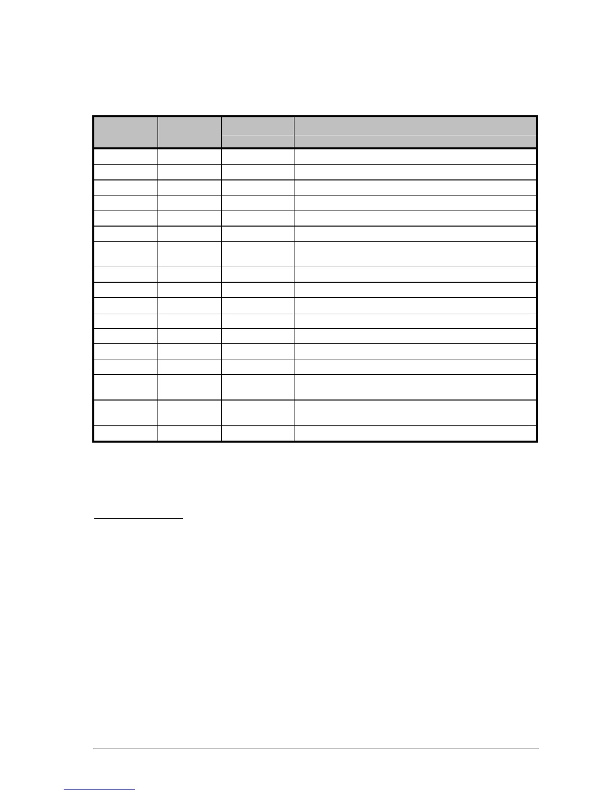
Wire assignment of C2 pigtail cable
Valid for cables with PN# 202 201 074, 202 201 075 and 202 201 076
Pin/Wire
No.
Wire Colour Signal Name Description
1 Brown SCL Clock line of I²C bus interface
2 Blue DO_0 (OUT1) Digital Output 1 (TTL)
3 White DI_4 (Z) Encoder input Z index (TTL)
4 Green DI_3 (B) Encoder input B track (TTL)
5 Pink DI_2 (A) Encoder input A track (TTL)
6 Yellow SDA Data line of I²C bus interface
7
Black AO
(LASER_AOUT) Output for analog modulation of illumination device (0 – 5 V DC)
8 Gray VCC_EXT camera supply voltage (10 – 24 V DC)
9 Red GND_EXT main camera ground
10 Violette RS232_RX RS-232 compatible input
11 Gray/Pink RS232_TX RS-232 compatible output
12 Red/Blue DO_1 (OUT2) Digital Output 2 (TTL)
13 White/Green DI_0 (IN1) Digital Input 1 (TTL)
14 Brown /Green DI_1 (IN2) Digital Input 2 (TTL)
15
White/Yellow
AIN
Input for monitoring specific functions of illumination device (0 – 5
V DC)
16
Yellow/ Brown DO_2
(LASER_DOUT) Output for digital modulation of illumination device (TTL)
17 White/Gray GND Reference ground for IO and Laser signals
(Note when using the C2 pigtail cable: I/O signals are not isolated. The maximum voltage level is
limited to 5 V. The outputs are not capable of load driving)
IMPORTANT NOTE: When using C2 power & I/O cables (standard or pigtail) with length longer than
20 m it is recommended to supply the camera with a voltage of 24 V
 Loading...