Ethernet Communications Modules, 3rd Edition, Rev. D
2–8
Chapter 2: Setup and Installation
1
2
3
4
5
6
7
8
9
10
11
12
13
14
A
B
C
D
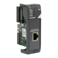
Inserting the ECOM Module in the PLC Base
H0 Series ECOM Module Installation
Before installing the option module in the DL05 option slot or any of the DL06 option slots,
set the Module ID dip switch (if your application requires this) on the H0 Series ECOM
module. Verify power to the PLC is turned off. The next step is to remove the protective option
slot cover. Remove the cover by squeezing the pinch tabs and lifting the cover off
Now, insert the module into the open slot on the DL05 or into any one of the four slots in the
DL06. Locate the module so the printed information is oriented in the same direction as the
markings on the PLC. Be careful to align the female connector on the printed circuit board of
the module with the male connector on the PLC mother board. Press the module into the slot
until the front of the module is flush with the front of the PLC. Check the DL06 power budget
to be sure that it remains within the power supply limits before installing more modules.
DL205 Slot Choices
The DL205 system supports placement of the ECOM module in the CPU-base only, not in
local expansion bases or remote I/O bases. The number of usable slots depends on how many
slots your base has. The module does not work in slot 0 of the DL205 series PLCs, the slot
next to the CPU. The D2-240, D2-250-1, D2-260 and D2-262 CPUs support the ECOM
modules. The D2-230 CPU does not support the ECOM modules.
WARNING: Your system can be damaged if you install or remove system components before disconnecting
the system power. To minimize the risk of equipment damage, electrical shock, or personal injury,
always disconnect the system power before installing or removing any system
Setup and
Installation
Installation and
Safety Guidelines
2--7
Setup and Installation
Ethernet Communications Modules, 3rd Edition Rev C, 06/11
Inserting the ECOM Module in the PLC Base
Before installing the option module in the DL05 option slot or any of the DL06 option
slots, set the Module ID dip switch (if your application requires this) on the H0 Series
ECOM module. The next step is to remove the protective option slot cover. Remove
the cover by squeezing the pinch tabs and lifting the cover off.
Pinch Tabs
C0 C4C2X1 X3 X4 X6 X11 X13X14 X16 X21 X23N.C.
C1 C3X2 X5 X7 X10 X12 X15 X17 X20 X22X 0 N. C.
AC
(
N
)
24V
0V
N.C.
C1 C3Y0 Y15Y12Y10 Y17Y7Y5Y2
C0 C2 Y16Y14Y13Y11Y6Y4Y3Y1
LGG
AC
(
L
)
2.0AOUTPUT: 6--240V
50 -- 60Hz2.0A,6 -- 27V
INPUT: 12 -- 24V3 -- 15mA
Y
X
40VA50--60HzPWR: 100-- 240V
0 1 2 3 4 5 6 7 10 11 12 13 14 15 16 17 20 21 22 23
PORT1 RUN STOP
PWR
RUN
CPU
TX1
RX1
TX2
RX2
D0--06DR
PORT2
TERM
Now, insert the module into the open slot on the DL05 or into any one of the four slots
in the DL06. Locate the module so the printed information is oriented in the same
direction as the markings on the PLC. Be careful to align the female connector on the
printed circuit board of the module with the male connector on the PLC mother
board. Press the module into the slot until the front of the module is flush with the
front of the PLC. Check the DL06 power budget to be sure that it remains within the
power supply limits before installing more modules.
The DL205 system supports placement of the ECOM module in the CPU-base only,
not in local expansion bases or remote I/O bases. The number of usable slots
depends on how many slots your base has. The module does not work in slot 0 of the
DL205 series PLCs, the slot next to the CPU. The D2--240, D2--250--1 and D2--260
CPUs support the ECOM modules. The D2--230 CPU does not support the ECOM
modules.
Slot 0 Slot 1 Slot 2 Slot 3 Slot 4
205
CPU
No!
WARNING: Your system can be damaged if you install or remove system
components before disconnecting the system power. To minimize the risk of
equipment damage, electrical shock, or personal injury, always disconnect
the system power before installing or removing any system component.
H0 Series ECOM
Module Installation
DL205 Slot
Choices
Setup and
Installation
Installation and
Safety Guidelines
2--7
Setup and Installation
Ethernet Communications Modules, 3rd Edition Rev C, 06/11
Inserting the ECOM Module in the PLC Base
Before installing the option module in the DL05 option slot or any of the DL06 option
slots, set the Module ID dip switch (if your application requires this) on the H0 Series
ECOM module. The next step is to remove the protective option s lot cover. Remove
the cover by squeezing the pinch tabs and lifting the cover off.
Pinch Tabs
C0 C4C2X1 X3 X4 X6 X11 X13X14 X16 X21 X23N.C.
C1 C3X2 X5 X7 X10X12 X15 X17 X20 X22X 0 N. C.
AC
(
N
)
24V
0V
N.C.
C1 C3Y0 Y15Y12Y10 Y17Y7Y5Y2
C0 C2 Y16Y14Y13Y 11Y6Y4Y3Y1
LGG
AC
(
L
)
2.0AOUTPUT: 6--240V
50 -- 60Hz2.0A,6 -- 27V
INPUT: 12 -- 24V3 -- 15mA
Y
X
40VA50--60HzPWR: 100--240V
0 1 2 3 4 5 6 7 10 11 12 13 14 15 16 17 20 21 22 23
PORT1 RUN STOP
PWR
RUN
CPU
TX1
RX1
TX2
RX2
D0--06DR
PORT2
TERM
Now, insert the module into the open slot on the DL05 or into any one of the four slots
in the DL06. Locate the module so the printed information is oriented in the same
direction as the markings on the PLC. Be careful to align the female connector on the
printed circuit board of the module with the male connector on the PLC mother
board. Press the module into the slot until the front of the module is flush with the
front of the PLC. Check the DL06 power budget to be sure that it remains within the
power supply limits before installing more modules.
The DL205 system supports placement of the ECOM module in the CPU-base only,
not in local expansion bases or remote I/O bases. The number of usable slots
depends on how many slots your base has. The module does not work in slot 0 of the
DL205 series PLCs, the slot next to the CPU. The D2--240, D2--250--1 and D2--260
CPUs support the ECOM modules. The D2--230 CPU does not support the ECOM
modules.
Slot 0 Slot 1 Slot 2 Slot 3 Slot 4
205
CPU
No!
WARNING: Your system can be damaged if you install or remove system
components before disconnecting the system power. To minimize the risk of
equipment damage, electrical shock, or personal injury, always disconnect
the system power before installing or removing any system component.
H0 Series ECOM
Module Installation
DL205 Slot
Choices
 Loading...