Step 4: Create a Project
In this step, we’ll create a simple project. e project assumes the presence of an I/O module
with discrete outputs. e project shown below is created by entering the ladder logic program
in the order that follows.
Rung #1
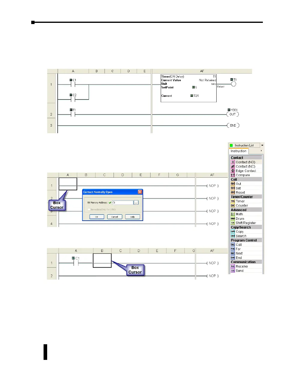
Place the Box Cursor on the rst position on Rung #1, as shown
below. From the Instruction List, click & drag a Contact (NO)
into this box. Enter C1 into the Bit Memory Address text box of
the Contact Normally Open dialog box that pops up and click OK.
A normally open contact labeled C1 will be placed in the beginning of Rung
#1.
e Box Cursor will move to the next available location.
Proceed to the next page to continue construction of Rung #1.
CLICK PLUS PLC Hardware User Manual, 1st Edition, Rev. K – C2-USER-M
1-10
Chapter 1: Getting Started