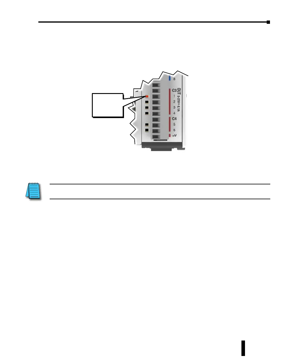
Step 11: Y001 Output On?
CLICK PLC output Y001 will turn on 5 seconds after you write the ON state to the C1 bit
using Data View in the Edit mode. e location and labeling of this output will depend on
your installed output modules.
If you missed viewing the transition of the Y001 status LED from OFF to ON, write an OFF
state to the C1 bit and then an ON state in the Data View Monitor to do it again.
NOTE: Also, try changing the status of the internal C2 bit. The results should be the same because the C2 bit is in
parallel with the C1 bit. The ladder logic reads: “Enable timer T1, if either C1 or ‘C2 is true.”
Congratulations!
You have now learned how to create, compile and transfer a ladder logic project to a CLICK
PLUS PLC, and then run and test the project. ere are additional instructions available for
the CLICK PLUS PLC. Please refer to the programming software online help topics for details
on these instructions.
Again, thank you very much for using the CLICK PLUS PLC system.
Y001
ON
CLICK PLUS PLC Hardware User Manual, 1st Edition, Rev. K – C2-USER-M
1-33
Chapter 1: Getting Started