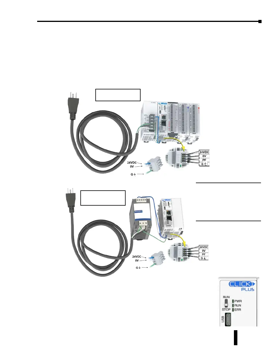
Step 6: Apply Power
e CLICK PLUS PLC system works with 24VDC power. ere is a small terminal block
on the bottom of the CLICK PLUS PLC unit. Wire the 24VDC output from a CLICK
power supply, or a properly sized and rated 24VDC power supply such as AutomationDirect’s
RHINO series, to the bottom terminal block (See Chapter 2: Specications for power supply
specications.)
EITHER
OR
Once you wire and power up the power supply, conrm the PWR
indicator (Green LED) on the CLICK PLUS PLC unit is on.
If the PWR indicator is not on, check the voltage on the terminal block
with a voltage meter. If you measure 24VDC on the terminal block,
the CLICK PLUS PLC unit may be defective. Please try another one or
contact us for a replacement.
Using an alternate
24VDC Power Supply.
Using a CLICK
24VDC Power Supply.
Power Terminal Block
Power Terminal Block
CAUTION:
DO NOT USE the PF connector.
Leave this terminal unconnected.
Connecting the PF terminal to
another device may cause damage
to the CLICK PLUS CPU.
CLICK PLUS PLC Hardware User Manual, 1st Edition, Rev. K – C2-USER-M
1-17
Chapter 1: Getting Started