N-35
SENSORS
CONTROLLERS
MOTION DEVICES
SOFTWARE
(J)
Temperature
Controllers
(K)
SSRs
(L)
Power
Controllers
(M)
Counters
(N)
Timers
(O)
Digital
Panel Meters
(P)
Indicators
(Q)
Converters
(R)
Digital
Display Units
(S)
Sensor
Controllers
(T)
Switching
Mode Power
Supplies
(U)
Recorders
(V)
HMIs
(W)
Panel PC
(X)
Field Network
Devices
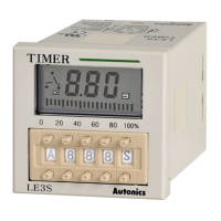
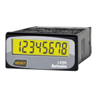
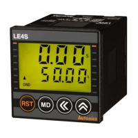
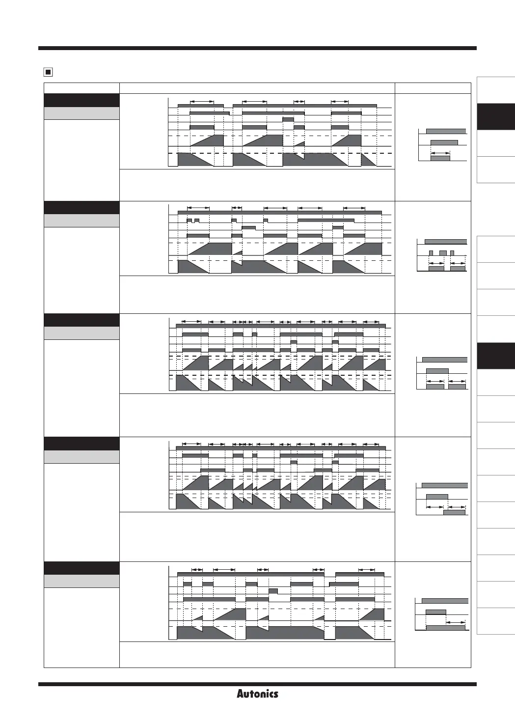
LCD Display Timer
LE4S Output Operation Mode
T = Setting time, T > Ta
※
Initial status: UP mode-display value is "0", output is "OFF". DOWN mode-display value is "setting time", output is "OFF".
Mode Time chart Operation
[
INT
]
POWER
START
RESET
RELAY OUT
Setting time
Setting time
0
0
UP
DOWN
T T
①
②
TTa
POWER
START
RELAY
OUT
T
INT
Interval
1. Output will be ON when START signal is ON at status of power on and Timing operation starts.
2. Output will be OFF when timing operation is progressed up to the setting time. Display value will be HOLD.
3. When RESET signal is ON, display value and output will be reset. (
①
position)
4. If RESET signal is OFF when START signal is ON,“STEP 1” will be restarted.
5. When START signal is OFF, display value and output will be reset. (
②
position)
[
INt1
]
POWER
START
RESET
RELAY OUT
Setting time
Setting time
0
0
UP
DOWN
T T T TTa
①
②
POWER
START
RELAY
OUT
T T
INT
Ⅰ
Interval 1
1. Output will be ON when START signal is ON at status of power on and Timing operation starts.
2. Output will be OFF when timing operation is progressed up to the setting time. Display value will be HOLD.
3. Even though START signal is applied repeatedly, only the initial signal is recognized. (
①
position)
4. If START signal is ON after timing operation is progressed up to the setting time, Output will be ON and setting
time will be reset and then timing setting starts.
5. When RESET signal is ON, display value and output will be reset. (
②
position)
[
NFD
]
POWER
START
RESET
RELAY OUT
ON Delay
ON Delay
OFF Delay
OFF Delay
0
0
UP
DOWN
① ②
To
To
ToTon TonTon TaTaTa Ta
POWER
START
RELAY
OUT
Ton To
ON OFF D
ON-OFF Delay
1. If START signal is ON when power is on, Output will be ON when timing operation is progressed up to the Ton
setting time (On-Delay). IF START signal is OFF, output will be ON when timing operation is progressed up to
the To setting time (OFF-Delay).
2. If START signal is applied repeatedly, output is ON and display value will be reset. (
①
position)
3. When RESET signal is ON, display value and output will be reset. When RESET signal is OFF while START
signal is ON, it will be operating as On-Delay. (
②
position)
4. It is able to set each To time and Ton time separately.
[
NFd1
]
POWER
START
RESET
RELAY OUT
ON Delay
ON Delay
OFF Delay
OFF Delay
0
0
UP
DOWN
① ②
To
To
ToTon TonTon TaTaTa Ta
POWER
START
RELAY
OUT
Ton To
ON OFF D
Ⅰ
ON-OFF Delay 1
1. If START signal is ON when power is on, timing operation starts. Output will be ON when timing operation is
progressed up to the Ton setting time (On-Delay). IF START signal is OFF, output will be ON when timing
operation is progressed up to the To setting time (OFF-Delay).
2. Output will be ON when START signal is ON and goes OFF during setting time and display value will be reset. (
①
position)
3. Output will be OFF when START signal is OFF and goes ON during setting time and display value will be reset. (
①
position)
4. When RESET signal is ON, display value and output will be reset. When RESET signal is OFF while START
signal is ON, it will be operating as On-Delay. (
②
position)
5. It is able to set each To time and Ton time separately.
[
OFD
]
POWER
START
RESET
RELAY OUT
Setting time
Setting time
0
0
UP
DOWN
T TTa Ta Ta
POWER
START
RELAY
OUT
T
OFF D
OFF Delay
1. If START signal is ON when power is on, output will be ON.
2. When START signal is OFF, timing operation starts. Output will be OFF when timing operation is progressed up
to the setting time. Display value will be HOLD.
3. When RESET signal is ON, display value and output will be reset.
T > Ta
T > Ta
T > Ta
T > Ta
T > Ta
T = set time
T = set time
Ton, To = set time
Ton, To = set time
T = set time
Setting time
Setting time
Setting time
Setting time
 Loading...