Press the “right” button to select the test mode. Press “Left”
Button to exit.
How to use
DC voltage (VDC):
Connect the probe clip (auxiliary ground lead) to the negative
pole, and connect the probe Tip to the measured voltage.
Resistance (OHM):
Connect the probe clip (auxiliary ground lead) to one side of
the Resistance being measured, and the probe tip to the other
side.
Diode / Continuity Test (DIO):
Connect the probe clip (auxiliary ground lead) to one side of
the Diode being measured, and the probe tip to the other side.
Meanwhile it will display the voltage and show positive and
negative of diode.
Current (AMP):
The probe is connected in series in the circuit under test, it will
display the current value.
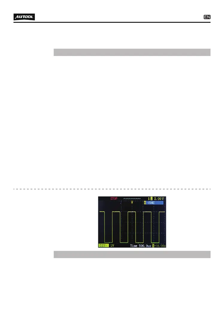
Frequency (HZ):
Display the frequency of the measured signal and duty cycle
value.
●
●
●
●
●
8
right are: DC voltage (VDC), resistance (OHM), diode/continui-
ty test (DIO), current (AMP), frequency (HZ).
Instructions
“START / STOP” (press “OK” to Start or Stop waveform
refresh).
“DIV” voltage per grid (test range 1~49V) press up and down
●
●
Oscilloscope
mode