17
●
●
●
●
●
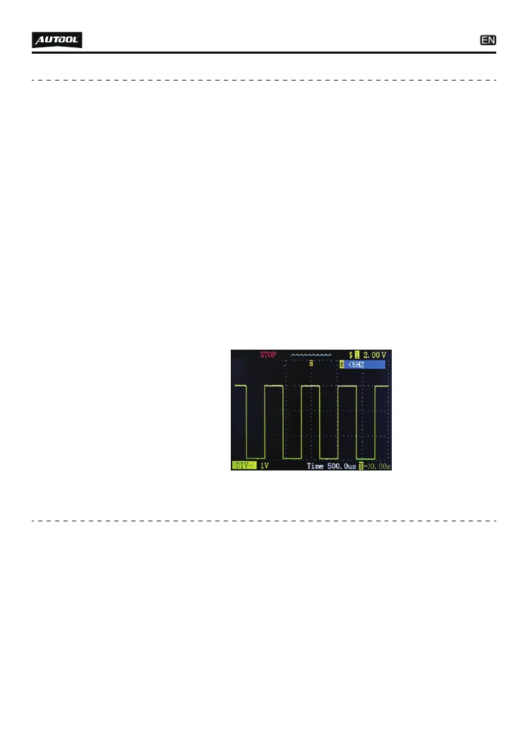
Enter into oscilloscope mode , use the probe tip with chassis
ground or auxiliary ground lead.
Connect the vacuum pump to M.A.P. sensor.
Touch the probe tip to the positive terminal of the M.A.P.
sensor and observe the LCD screen. Generally it should be
with a Sine Waveform in good condition.
Apply vacuum pump.
Release the vacuum pump and observe the reading on the
LCD screen.
If the waveform reading is abnormal, there should be a problem
with this sensor.
Use an OBD2 Scanner to read out the FAULT CODE (DTC) from
the vehicle and found the problem is with some kind of sensor
circuit, there is a fast way to testing the sensors conditions with
this probe.
For example, if you suspect that the problem is with the MAP
sensor circuit of the vehicle, follow this procedure to testing the
sensor.
Signal circuit
testing
(Oscilloscope
test)
●
●
●
Hook up the battery clip to power supply.
Enter into component activation, select MOMENT modefunc-
tion.
Connect the auxiliary ground lead to the negative terminal of
the component being tested, Connect the probe tip to the
positive terminal of the component, press “up” button to trigger
activation test.
For Example: Test a bulb working condition
Activating
components
in your hand