3
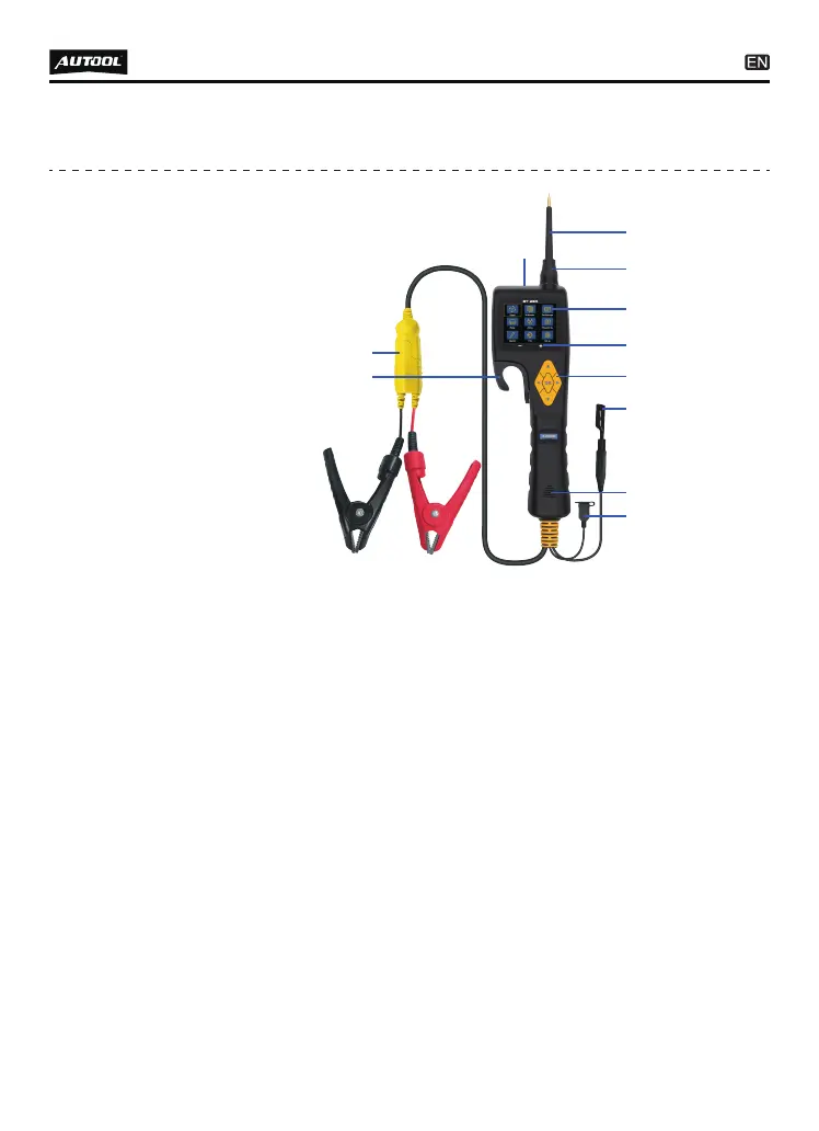
PRODUCT STRUCTURE
Structure
diagram
C
D
E
F
J
K
I
G
H
A
B
A - Probe Tip – Contact the circuit or component for testing.
B - Front LED Light – Used for lighting in dark working areas
or when working at night.
C - LCD Screen – Display test results.
D - Red / Green LED Indicator – Positive and negative
indicator light.
E - Key Button Operation – 5 Keys Navigating for fast
operation.
F - Auxiliary Ground Lead – Auxiliary clip of ground lead
(probe negative).
G - Speaker – Buzzer for warning or remind.
H - USB Port – Update by connect PC with USB cable to
probe.
I - Relay Test Port – Connect the relay test cable.
J - Power Connector – Connect the battery clip to the car
battery and extension cable.
K - HOOK – Hook the probe in a suitable place to avoid broken
and convenient in use.
●
●
●
●
●
●
●
●
●
●
●