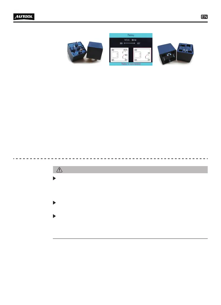
For example, Test a 5-terminal relay
* The relay test result will be displayed at the bottom.
The component activation function is designed to generate activa-
tion signals to the tested components, such as activating lights,
motors and other on-board electric equipment.
10
●
●
●
●
●
●
●
Connect the relay test wire to probe.
Connect the black wire to the relay terminal 30#.
Connect the green wire to the relay terminal 87A#.
Connect the red wire to the relay terminal 87#.
Connect the auxiliary ground wire (negative clip) to terminal
86#.
Connect the Probe Tip to the relay terminal 85#.
Press the “UP” button to trigger the test.
(5-terminal relay) (Test Results) (4-terminal relay)
Component
activation
The activation mode is only designed for supply powers or
ground, and cannot be used for any sensitive electronics
equipment (such as ECU, sensor module), otherwise there is a
risk of burning out components.
Do not perform any tests on any ECU module, SRS (air bag)
system before the system is completely disabled or unplugged.
Supply power to electrical system will cause damage to the
vehicle’s sensitive electronic components, so we strongly
recommend that you refer to the vehicle manufacturer’s sche-
matic diagram and diagnostic process.
NOTE: