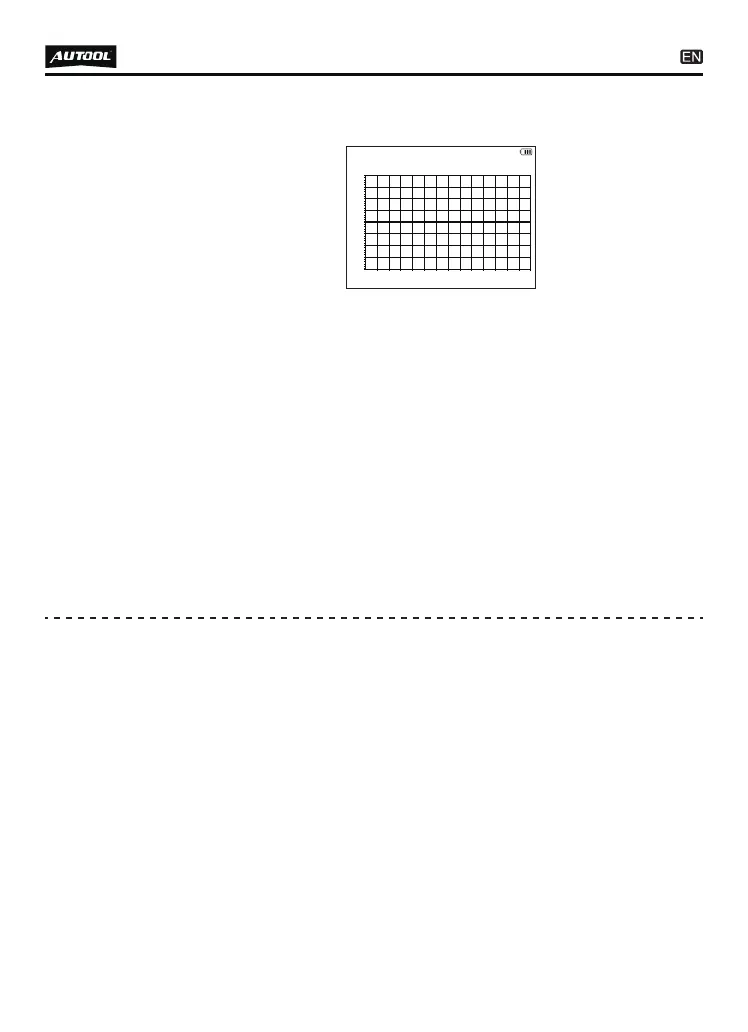
5V/di v
100uS
0V
SENSOR: Min: 0.00V Max: 0.00V
0 RPM 4STROKE
23
Press [up / down] keys to adjust the waveform amplitude.
Press [left / right] keys to adjust the time value.
Press [F1] to select the engine cylinder type and ignition, which
is used to calculate the engine speed. The option “distributor”
represents the high-voltage signal on the distributor of the old
engine, the option “2-stroke” represents the cylinder ignition
pulse signal of the two-stroke engine, and the option “4-stroke”
represents the ignition pulse signal of the four stroke engine;
The speed value shown is the engine speed value calculated
from the single cylinder ignition pulse signal. During the test,
the sensor head shall be close to an ignition wire or an ignition
coil of a cylinder, and not close to two or more ignition pulse
signal wires. If multiple ignition wires are arranged together, the
position close to the spark plug can be selected for detection.
●
●
●
●
Insert the multi-function detection line into the multi-function
interface (the top of the machine). The “K line” identification
line connects the extension wire and probe; the “ground wire”
identification line connects the extension wire and probe; the
ground wire probe is connected to the ground wire end of the
vehicle circuit (such as the 5 pin of the standard OBD-II), and
the K line probe is connected to the K line bus in the vehicle
circuit. Note to distinguish K lines on the automotive circuit. For
example, the 7-pin of the standard OBD-II is K line, and there
are multiple K lines in the car for connecting various low-speed
electrical appliances in the car.
●
K line data
Enter the function item, displayed as shown below:
●