C01 - CAN+
C01 - CAN-
C01 - GND
C01
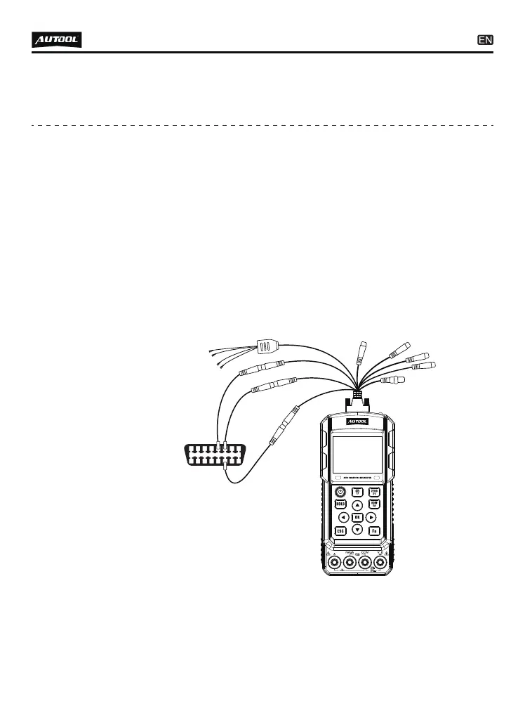
Insert the multi-function detection line into the multi-function
interface (the top of the machine). The “CAN+” identification
line connects the extension wire and probe; the “CAN -” identi-
fication line connects the extension wire and probe; the
“ground wire” identification line connects the extension wire
and probe; the ground wire probe is connected to the ground
wire end of the vehicle circuit (such as the 5 pin of the standard
OBD-II); the CAN+ wire probe is connected to the bus CANH
in the vehicle circuit; the CAN wire probe is connected to the
bus CANL in the vehicle circuit. Note to distinguish the CAN
lines on the car circuit. For example, 6 pin of the standard
OBD-II is CANH line and 14 pin is CANL line. The car interior
also has a multiple CAN bus to connect the various electronic
controllers inside the car.
●
●
CAN bus data
25
The instrument can test CAN bus Baud rate 500K / 250K / 125K
/ 100K / 83.33K / 50K / 33.33K. If there is no baud rate that the
user needs, please contact the manufacturer to customize the
non-standard products.
Enter the function item, displayed as shown below:
●
●
Press the [left / right] keys in the receiving state to change the
baud rate of communication.