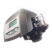
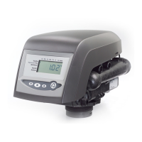
Figure 1 Autotrol Series 256 Bypass Valve
3
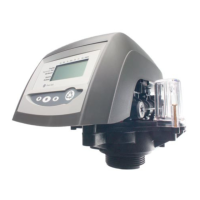
Figure 2 Typical globe valve bypass system
Installation
All plumbing must conform to local codes.
Inspect unit carefully for carrier shortage or shipping
damage.
Location Selection
1. The distance between the unit and a drain should
be as short as possible.
2. If it is likely that supplementary water treating
equipment will be required, make certain adequate
additional space is available.
3. Since salt must be added periodically to the brine
tank, the location should be easily accessible.
4. Do not install any unit closer to a water heater than
a total run of 10 feet (3 m) of piping between the
outlet of the conditioner and the inlet to the heater.
Water heaters can sometimes overheat to the
extent they will transmit heat back down the cold
pipe into the unit control valve.
Hot water can severely damage the conditioner.
A 10 foot (3 m) total pipe run, including bends,
elbows, etc., is a reasonable distance to help
prevent this possibility. A positive way to prevent
hot water from flowing from heat source to the
conditioner, in the event of a negative pressure
situation, is to install a check valve in the soft water
piping from the conditioner. If a check valve is
installed, make certain the water heating unit is
equipped with a properly rated temperature and
pressure safety relief valve. Also, be certain that
local codes are not violated.
5. Do not locate unit where it or its connections
(including the drain and overflow lines) will ever be
subjected to room temperatures under 34° F (1°C)
or over 120° F (49°C).
6. Do not install unit near acid or acid fumes.
7. The use of resin cleaners in an unvented enclosure
is not recommended.
Water Line Connection
The installation of a bypass valve system is recommended
to provide for occasions when the water conditioner must
be bypassed for hard water or for servicing.
The most common bypass systems are the Autotrol
Series 256 Bypass Valve (Figure 1) and plumbed-in
globe valves (Figure 2). Though both are similar in
function, the 256 Autotrol Bypass offers simplicity and
ease of operation.
Not in Bypass In Bypass
Water Water
Conditioner Conditioner
Not in Bypass In Bypass
Water Water
Conditioner Conditioner
Drain Line Connection
1. Ideally located, the unit will be above and not more
than 20 feet (6.1 m) from the drain. For such installa-
tions, using an appropriate adapter fitting (not
supplied), connect 1/2 inch (1.3 cm) plastic tubing
to the drain line connection of the control valve.
2. If the unit is located more than 20 feet (6.1 m) from
drain, use 3/4-inch (1.9 cm) tubing for runs up to 40
feet (12.2 m). Also, purchase appropriate fitting to
connect the 3/4-inch tubing to the 1/2-inch NPT
drain connection.
3. If the unit is located where the drain line must be
elevated, you may elevate the line up to 6 feet (1.8 m)
providing the run does not exceed 15 feet (4.6 m)
and water pressure at conditioner is not less than 40
psi (2.76 bar). You may elevate an additional 2 feet
(61 cm) for each additional 10 psi (.69 bar).
4. Where the drain line is elevated but empties into a
drain below the level of the control valve, form a 7
inch (18 cm) loop at the far end of the line so that
the bottom of the loop is level with the drain line
connection. This will provide an adequate siphon
trap.
5. Where the drain empties into an overhead sewer
line, a sink-type trap must be used.
18
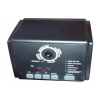
Troubleshooting
The technology upon which the Series 255 control is based is well established and proven in service over many
years. However, should a problem or question arise regarding the operation of the system, the control can be very
easily serviced. The control module can be quickly replaced or adjustments can be made at the installation. For
parts mentioned, refer to exploded views in the Replacement Parts section of this manual.
Problem Possible Cause Solution
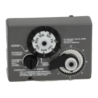
1.Control will not regenerate a. Transformer or motor not connected. a.Connect power.
automatically. b.Defective timer motor. b.Replace motor.
c. Skipper pins not down on timer skipper c. Depress pins for days regeneration
wheel. required.
d.Binding in gear train of timer. d.Replace timer.
2.Control regenerates at wrong a. Time set incorrectly. a. Correct time setting according
time of day. to instructions.
3. Control will not draw brine. a. Low water pressure. a. Set pump to maintain 20 psi at softener.
b.Restricted drain line. b.Change drain to remove restriction.
c. Injector plugged. c. Clean injector and screen.
d.Injector defective. d.Replace injector.
e. Valve disc 2 and/or 3 not closed. e. Remove foreign matter from disc and check
disc for closing by pushing in on stem.
Replace if needed.
f. Air check valve closes prematurely. f. Put control momentarily into brine/slow rinse.
Replace or repair air check if needed.
g.Timer locking pin not horizontal g.Turn to horizontal position.
4.Brine tank overflow. a. Brine valve disc 1 being held open a. Manually operate valve stem to flush
by foreign matter. away obstruction.
b.Uncontrolled brine refill flow rate. b.Remove brine control to cleanball and
seat.
c. Valve disc 2 not closed during brine c. Flush out foreign matter holding disc
draw causing brine refill. open by manually operating valve stem.
d. Air leak in brine line to air check. d. Check all connections in brine line for
leaks. Refer to instructions.
e. Improper drain control for injector. e. Too small of a drain control with a "B" or
"C" injector will reduce draw rates. See
Pressure Graphs.
f. Drain control clogged with resin or f. Clean drain control.
other debris.
5.System using more or less salt a.Foreign matter in controller causing a.Remove brine control and flush out
than salt dial setting. incorrect flow rates. foreign matter. Manually position control
to brine/slow rinse to clean controller
(after so doing position control to “purge”
to remove brine from tank)
b.Defective controller. b.Replace brine control.
6. Intermittent or irregular brine draw. a. Low water pressure. a. Set pump to maintain 20 psi at softener.
b. Defective injector. b.Replace injector.
7.No conditioned water after a.No salt in brine tank. a.Add salt to brine tank.
regeneration. b.Injector plugged. b.Clean injector and screen.
c. Air check valve closes prematurely. c. Put control momentarily into brine/slow rinse.
Replace or repair air check if needed.
 Loading...