2
Introduction
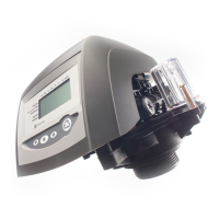
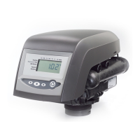
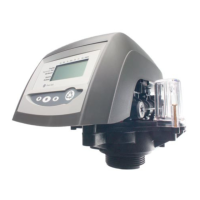
The Series 255 control system combines design
simplicity with NORYL* construction to provide the
user with an uncommonly reliable appliance. The
inherent reliability of the system means a long life of
efficient, trouble-free, uninterrupted soft water luxury.
Should maintenance become necessary, the Series 255
control system offers a unique “separation” capability
illustrated in this manual.
Of interest to the owner and water conditioning dealer
are the design and operation benefits detailed below.
Superior Design
• Fewer parts than any control system of comparable
function and most controls of lesser function.
• Single synchronous low voltage electric motor
provides all the power for the clock 440i timer and
the operation of the control.
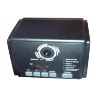
• Program clock (timer) provides guest regeneration
capabilitiy.
• Control may be indexed manually with or without
power to its service or regeneration positions. Legend
on timer face plate indicates control valve position.
• No moving parts in water stream means no close
tolerance components subject to fouling. Thus, the
system is especially effective on iron-bearing water.
• No dynamic seals that could cause leakage
through wear or fatigue.
• Control accepts NORYL or brass manifold or
modular bypass valve without modification,
offering complete versatility and easy plumbing for
any installation.
• Brining control valve built into system eliminates
need for an external brine valve.
• Automatic drain flow controller is incorporated in
the system.
Superior Operation
• Direct acting system functions independently of
water pressure. No pistons or diaphragms that
require a minimum water pressure to operate.
• Five-cycle operation provides for downflow
service, upflow backwash, downflow brining,
downflow rinse, downflow purge (fast rinse). A sixth
position is included for timed refill of the brine tank.
• Valve discs are held closed by water pressure
and therefore, are leak tight. The sealing forces are
increased as the water pressure is increased. Valve
seats are in a vertical position, which is the design
position least vulnerable to plugging.
• System operation cannot get out of phase or
sequence. Control always returns to a fixed service
position after regeneration regardless of where in
the regeneration cycle it was started.
• Bypass water is automatically available during
regeneration.
Table of Contents
Introduction ...................................................... 2
Superior Design
Superior Operation
Installation ........................................................ 3
Location Selection
Water Line Connection
Drain Line Connection
Overflow Line Connection
Electrical Connection
Increasing the Length of the
Transformer Cord ............................................ 5
Placing Conditioner into Operation ............... 5
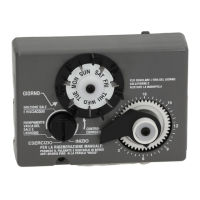
Adjustment of Timer ........................................ 6
Special Features of Timer ............................... 7
Adjustment of Brine Control........................... 7
How to Set the Salt Dial
Removing the Series 255
Control Module for Servicing ......................... 8
Preventive Maintenance.................................. 9
Specifications................................................. 10
Pressure Graphs ............................................ 11
Flow Diagrams ............................................... 12
Replacement Parts ........................................ 14
Troubleshooting ............................................. 18
Disinfection of Water Conditioners.............. 19
* NORYL is a Trademark of General Electric Company
19
Disinfection of Water Conditioners
The materials of construction of the modern water
conditioner will not support bacterial growth, nor will
these materials contaminate a water supply. However,
the normal conditions existing during shipping, storage
and installation indicate the advisability of disinfecting
a conditioner after installation, before the conditioner
is used to treat potable water. In addition, during
normal use, a conditioner may become fouled with
organic matter, or in some cases, with bacteria from
the water supply.
Thus every conditioner should be disinfected after
installation, some will require periodic disinfection
during their normal life, and in a few cases disinfection
with every regeneration would be recommended.
Depending upon the conditions of use, the style of
conditioner, the type of ion exchanger, and the disin-
fectant available, a choice can be made among the
following methods.
Sodium or Calcium Hypochlorite
Application
These materials are satisfactory for use with polystyrene
resins, synthetic gel zeolite, greensand and bentonites.
5.25% Sodium Hypochlorite
These solutions are available under trade names such as
Clorox, Linco, Bo Peep, White Sail and Eagle Brand
Bleach. If stronger solutions are used, such as those sold
for commercial laundries, adjust the dosage accordingly.
1. Dosage
a. Polystyrene resin; 1.2 fluid ounce per cubic foot.
b. Non-resinous exchangers; 0.8 fluid ounce per
cubic foot.
2. Brine tank conditioners
a. Backwash the conditioner, and add the required
amount of hypochlorite solution to the brine well
of the brine tank. (The brine tank should have
water in it to permit the solution to be carried into
the conditioner.)
b. Proceed with the normal regeneration.
Calcium Hypochlorite
Calcium hypochlorite, 70% available chlorine, is
available in several forms including tablets and gran-
ules. These solid materials may be used directly,
without dissolving before use.
1. Dosage
a. 2 grains (approximately 0.1 ounce) per cubic foot.
2. Brine tank conditioners
a. Backwash the conditioner and add the required
amount of hypochlorite to the brine well of the
brine tank. (The brine tank should have water in it
to permit the chlorine solution to be carried into
the conditioner.)
b. Proceed with the normal regeneration.
Problem Possible Cause Solution
8.Control backwashes or purges at a.Incorrect drain controller used. a.Replace with correct size drain controller.
excessively low or high rate.
b. Foreign matter affecting controller operation. b. Remove drain controller and clean ball and seat.
9. Flowing or dripping water at drain a.Drain valve (5 or 6) or brine valve (1) a.Manually operate valve stem to flush
or brine line after regeneration. held open by foreign matter or particle. away obstruction.
b.Valve stem return spring weak. b.Replace spring.
10. Hard water leakage after a.Improper regeneration. a. Repeat regeneration making certain
regeneration correct salt dosage was set.
b.Leaking of external bypass valve. b.Replace o-ring.
c. O-ring around riser pipe damaged. c.Replace o-ring.
d.Leaking past bypass valve disc. d.Replace valve disc.
 Loading...