5
Placing Conditioner into Operation
After all previous steps have been completed, the unit
is ready to be placed into operation. Follow these
steps carefully.
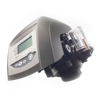
1. Remove control valve cover (Figure 10A).
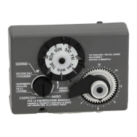
Note: The following steps will require turning the
pointer knob, (Figure 8), to various positions. Insert
a wide blade screwdriver into arrow slot in pointer
knob and press in firmly. With knob held in, rotate
COUNTERCLOCKWISE only until arrow or knob
points to desired position. (Rotation is made much
easier if you grasp the camshaft with your free hand
and turn it at the same time.) Then permit knob to
spring back out.
2. Insert screwdriver into slot in pointer knob, (Figure 8).
Press in and rotate knob COUNTERCLOCKWISE
until arrow points directly to the word BACKWASH.
3. Fill resin tank with water.
A. With water supply off, place the bypass valve(s)
into the "not in bypass" position.
B. Open water supply valve very slowly to approxi-
mately the 1/4 open position.
Important
If opened too rapidly or too far, resin may be
lost. In this position, you should hear air
escaping slowly from the drain line.
C. When all of the air has been purged from the
tank(water begins to flow steadily from the drain),
open the water supply valve all the way.
D. Allow water to run to drain until clear.
E. Turn off water supply and let the unit stand for
about 5 minutes. This will allow all trapped air to
escape from the tank.
4. Add water to brine tank (initial fill).
With a bucket or hose, add approximately 4 gallons
(15 liters) of water to brine tank. If the tank has a
salt platform above the bottom of the tank, add
water until the level is approximately 1inch (25 mm)
above the platform.
Increasing the Length of the
Transformer Cord
If it is necessary to extend the length of the transformer
cord, an optional 15 foot (4.6 m) extension is available,
(see Figure 5) or the cord may be spliced as follows:
1. Strip insulation from wire 5/16-inch(8mm) from wire
end.
2. Insert stripped wire into barrel of connector and
crimp. For best results, crimp twice per wire as
shown (Figure 6).
Splice connectors or extension wire is not supplied.
They are available at hardware or electrical stores.
Figure 5
50 feet(15.24m) maximum, 18 AWG solid
or stranded insulated copper wire.
Figure 6
Splice Connector
(22-18 AWG)
16
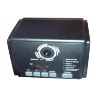
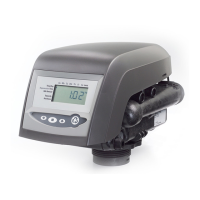
440i Timer
Bypass Valve
Piping Boss
Note: Do not use pipe joint compound
when threading pipe into the Noryl piping
boss. Use only Teflon
®
pipe tape. Do not
overtighten pipe into Noryl piping boss.
* Teflon is a registered Trademark of E. I.
Dupont Nemours and Co.
B
Y
P
A
S
S
B
Y
P
A
S
S
2
2
1
2
3
4
5
6
7
8
9
3
1
1
 Loading...