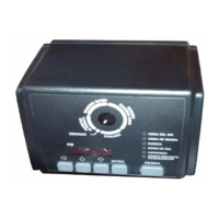
TO SET TIME OF DAY
PULL KNOB AND ROTATE
MANUAL REGENERATION:
PRESS KNOB AND TURN CLOCKWISE
TO “START” –
RELEASE
DAY
BRINE/
SLOW RINSE
FAST RINSE/
BACKWASH
START
REFILL
CONDITIONED
WATER
6PM
3PM
9AM3AM
6AM
NOONMIDNIGHT
1
7
6
5
4
3
2
6
5. Put into operation.
A. Open water supply valve slowly to full open
position.
B. Carefully advance pointer knob COUNTER-
CLOCKWISE to center of FAST RINSE/REFILL
position and hold there until air check (Figure 7) fills
with water and water starts to flow through brine
line into brine tank. Do not run for more than 2
minutes.
C. Advance pointer knob COUNTERCLOCKWISE
until arrow points to the center of the BRINE/SLOW
RINSE position.
D. With the conditioner in this position, check to
see if water is being drawn from the brine tank. The
water level in the brine tank will recede very slowly.
Observe for at least 3 minutes. If the water level
does not recede or goes up, or if air enters the
transparent air check chamber and the ball falls
and seats, reference Troubleshooting section.
E. Advance pointer knob COUNTERCLOCKWISE
to CONDITIONED WATER.
F. Run water from a nearby faucet until the water is
clear and soft.
Figure 7
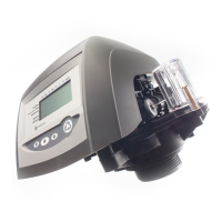
Control Valve
Air Check Check Female
Ball Elbow
1. Set days of regeneration on skipper wheel (Figure 8).
• Pull all skipper pins outward (away from control).
• Rotate skipper wheel until day arrow points to
current day or number 1.
• Depress skipper pin(s) at day(s) for which
regeneration is desired.
2. Set the time of day .
• Grasp timer knob and pull outward.
• Rotate in either direction until the timer arrow
points to the actual time of day (Figure 8).
• Release timer knob .
Note: With the time of day properly set, the conditioner
will regenerate at about 2:30 a.m. If you prefer to have
the unit regenerate at an earlier or later time, simply set
the current time-of-day accordingly. (e.g., To have the
unit REGENERATE/BACKWASH at 4:30 a.m. - 2 hours
later -set the clock 2 hours earlier than the actual
current time).
Note: The Timer Locking Pin should always be horizon-
tal (Figure 8) during operation.
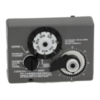
Figure 8
Skipper Wheel
Skipper Pins
Day Arrow
Time Arrow
Pointer Knob
Timer Knob
Adjustment of Timer
Brine
Line
Timer
Locking Pin
15
Part
Code No. Description Qty.
13 1010429 O-Ring BN 1
14 1010428 O-Ring EP 1
15 Locking Bar: 1
1031402 English Language
1031403 French Language
1031404 German Language
1031405 Italian Language
1031406 Japanese Language
1031407 Spanish Language
16 1006093 Screw, No. 8 x 9/16 in 1
17 1001580 Spring, Valve Discs 9
18 1032565 Valve Cover, Standard, Black 1
19 1000062 i-Lid Cover 1
20 1000297 Extended Connector 1
(For use with i-Lid Cover)
21 High Style Covers:
1041087 Beige/Brown
1041088 Black/White
1041091 Beige/Black
Kits:
22 1033066 New to Old Aircheck Adapter
23 1001404 O-Ring Group: Tank Adapter
1010117 (1), 1010407 (1),
1010410 (4)
24 1040459 O-Ring Group: Piping Boss
1010431 (1), 1010411 (2)
25 1041010 13/16 Rubber Insert (Optional)
Valve Discs:
* 1000250 Standard
* 1000252 Severe Service
Valve
Part
Code No. Description Qty.
1 1000232 Valve Assembly, 1
w/o Flow Controls
2 Camshaft: 1
1031950 Standard, One-Piece
1033024 Standard, Segmented
1033025 Extra Salt, Segmented
1033026 Long Rinse, Segmented
1032969 Water Saver, Segmented
3 1030501 Camshaft Bearing 1
4 1031391 Timer Locking Pin 1
5 1000226 Screen/Cap Assembly 1
with O-Ring
6 Drain Control Assembly 1
with O-Rings:
1000209 No. 7 (1.2 gpm; 4.5 lpm)
1000210 No. 8 (1.6 gpm; 6.1 lpm)
1000211 No. 9 (2.0 gpm; 7.6 lpm)
1000212 No. 10 (2.5 gpm; 9.5 lpm)
1000213 No. 12 (3.5 gpm; 13.2 lpm)
1000214 No. 13 (4.1 gpm; 15.5 lpm)**
1000215 No. 14 (4.8 gpm; 18.2 lpm)**
7 1030502 Ball, Flow Control 2
8 Brine Refill Control: 1
1034261 1 to 10 lbs Salt
1034263 3 to 19 lbs Salt
9 Injector Assembly 1
with O-Rings:
1032970 "A" Injector - White
1032971 "B" Injector - Blue
1032972 "C" Injector - Red
10 Injector Cap with O-Ring: 1
1000217 "A" Cap
1000218 "B" Cap
1000219 "C" Cap
11 1033784 Tank Adapter Assembly 1
12 1032416 Air Check Kit 1
*Not Shown
**Flow control does not use Flow Control Ball (1030502).
 Loading...