EQUIPMENT INSTALLATION 23
Rev A
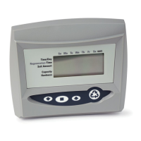
Regeneration Cycle Indicators
C0 = Treated Water - normal operation mode
C1 = Backwash Cycle
C2 = Regenerant Draw Cycle (not used in filter mode)
C3 = Slow Rinse Cycle (not used in filter mode)
C4 = System Pause
C5 = Fast Rinse Cycle 1
C6 = Backwash Cycle 2 (not used in filter mode)
C7 = Fast Rinse Cycle 2 (not used in filter mode)
C8 = Regenerant Refill (not used in filter mode)
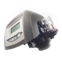
Valve Disc Operation
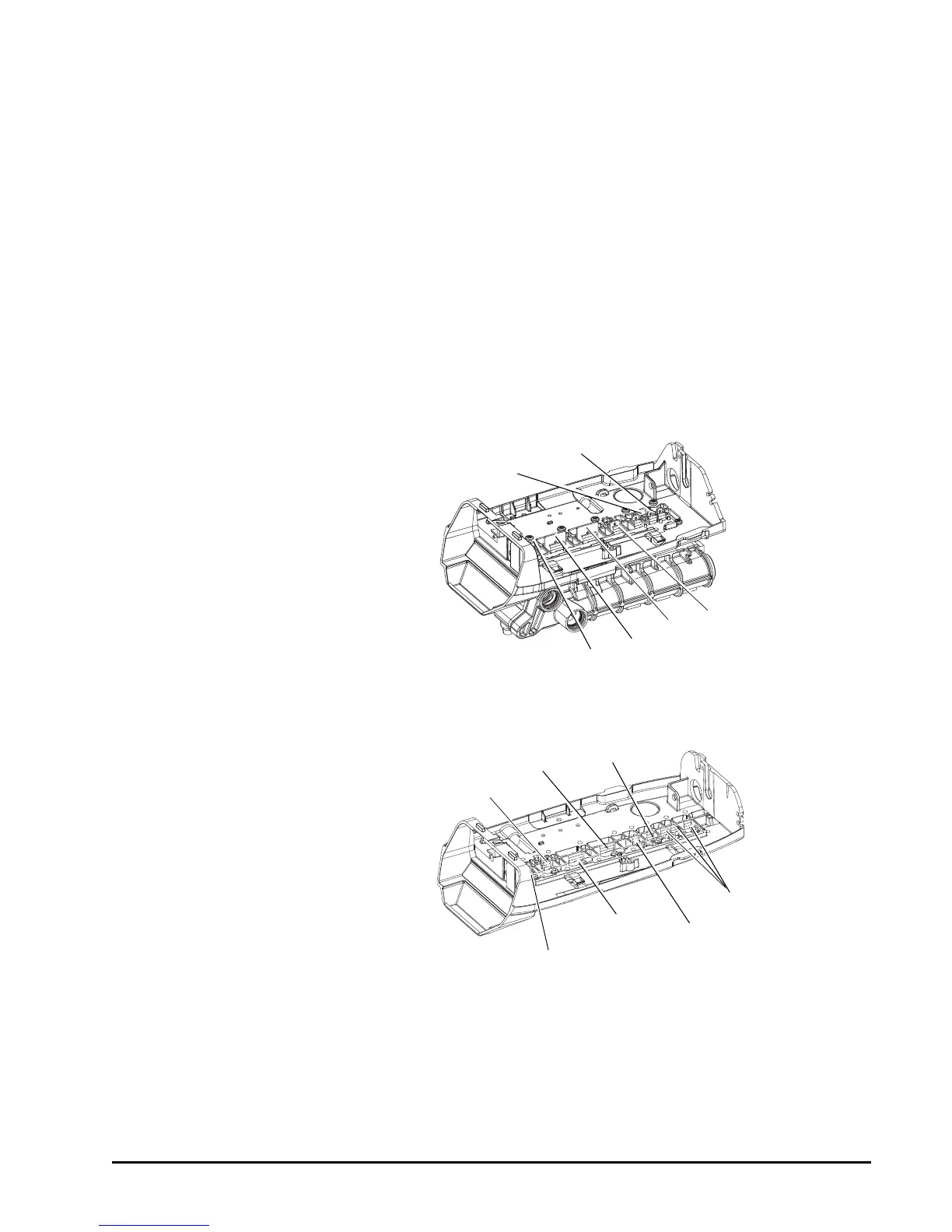
Figure 14 - 255 Valve
Figure 15 - Performa Valve (263, 268)
1 Regenerant
2 Inlet
4 Bypass
3 Outlet
5 Rinse Drain
6 Backwash/Drain
1 Regenerant Valve
2 Bypass Valve
3 Inlet Valve
4 Outlet Valve
5 Refill Valve
7 Backwash Drain Valves
6 Rinse Drain
 Loading...