Chapter 7: Installation reference
About this task
This section provides reference information for the Avaya Ethernet Routing Switches.
RJ-45 connector pin assignments
The following section outlines the connector pin assignments for the RJ-45 connectors in the
Avaya Ethernet Routing Switch 5000 Series switches.
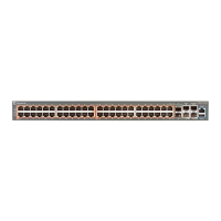
Avaya Ethernet Routing Switch 5600 non-PoE
The following table outlines the RJ-45 connector pin assignments in the Avaya Ethernet
Routing Switch 5600 Series non-PoE switches.
Connector
Pin
Number
Signal for
10/100Base-T MDI
configuration
Signal for
10/100Base-T MDI-X
configuration
1 Output transmit data
+ (TX+)
Input receive data +
(RX+)
2 Output transmit data -
(TX-)
Input receive data -
(RX-)
3 Input receive data +
(RX+)
Output transmit data +
(TX+)
6 Input receive data +
(RX+)
Output transmit data +
(TX+)
4, 5, 7, 8 Not used Not used
Pin
Number
Signal for 1GBase-T
MDI configuration
Signal for 1GBase-T
MDI-X configuration
1 TP0+ TP1+
2 TP0- TP1-
3 TP1+ TP0+
4 TP2+ TP3+
Installing Avaya Ethernet Routing Switch 5000 Series December 2013 75

 Loading...


