Procedure: Software Installation
Issue 6 September 2001
2-11
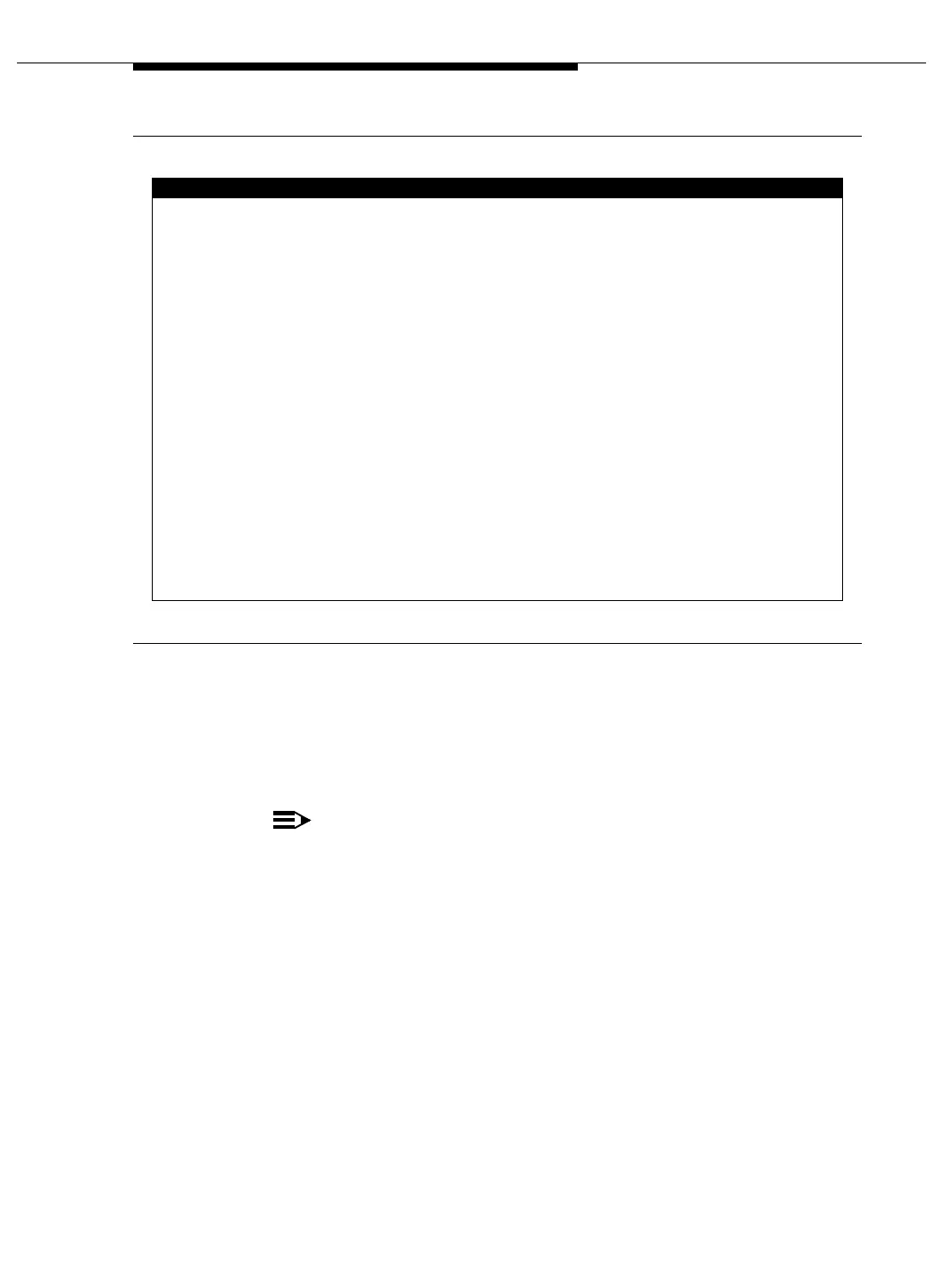
Figure 2-8. System Configuration Form
22. Verify that the Radio Controller value in the Board Type field is associated
with the proper slots. If this is not the case, repeat Step 18.
23. For each RC circuit pack logically or physically inserted, execute the add
radio-controller PPCSS command to generate the following screen.
NOTE:
PPCSS indicates the port network, carrier, and slot address where
the circuit pack is located; for example, 01A01 comprises port
network 1, carrier A, slot 01. See the “Radio Controller Circuit Pack
Form Fields” table in this chapter for additional information.
list configuration all
SYSTEM CONFIGURATION
Board
Page 1
Assigned Ports
u=unassigned t=tti p=psa
01B01
Number Board Type Code Vintage
EXPANSION INTRFC 000008
01B02
01B03
01B04
01B07
01B08
AUXILIARY TRUNK
DATA LINE
MAINTENANCE/TEST
TIE TRUNK
DS1 INTERFACE
000005
000012
000006
000006
000006
TN763C
TN726
TN771D
TN760B
TN464F
u u u u
u u u u u u u u
u 02 03 04
01 u u u u u u u
u u u u
01 02 03 04 05 06 07 08
09 10 11 12 13 14 15 16
TN570
01B05 DID TRUNK TN753 000016
no board u u u u u u u u
u u u u u u u u
u u u u u u u u
17 18 19 20 21 22 23 24
u u u u u u u u
0A uno boardRADIO CONTROLLER01B10
01B06 DS1 INTERFACE

 Loading...