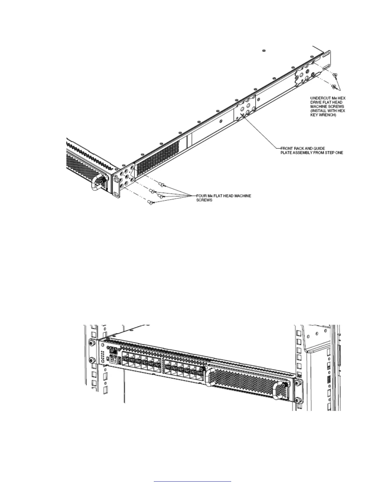
Figure 11: Attach guide brackets
a. Use four M4 flat-head Phillips machine screws to attach the front of each guide bracket
to the switch chassis.
b. Use two M4 low-profile undercut flat-head hex machine screws to attach the rear of
each guide bracket to the switch chassis.
c. Verify that the rear screws sit flush in the guide brackets.
d. Test fit the rear mounting brackets in the guide brackets and verify that the rear
brackets can slide in the channels. Remove the rear brackets.
3. Install the switch into the equipment rack, temporarily using only the front rack mounts and
screws.
Figure 12: Install switch in rack using front rack mounts
Switch installation
32 Installing Avaya VSP 7000 Series August 2014
Comments? infodev@avaya.com

 Loading...