17
General
F-FEM-CNT — User’s Guide
2.5 Cascade
The F-FEM-CNT is part of a family of Front End Modules that operate together
on a network:
An interface up to 400 MBaud IEEE1394 is used to connect them for data trans-
mission.
The F-FEM-DIO is connected via a serial interface to F-FEM modules of other
types (F-FEM-CON, -DAC, -CNT).
Several F-FEM modules can be connected to form a whole system via the IEEE
bus. The restrictions on the number of nodes, sampling rate and number of
channels depend on the license and the version of the PUMA Open software in
use.
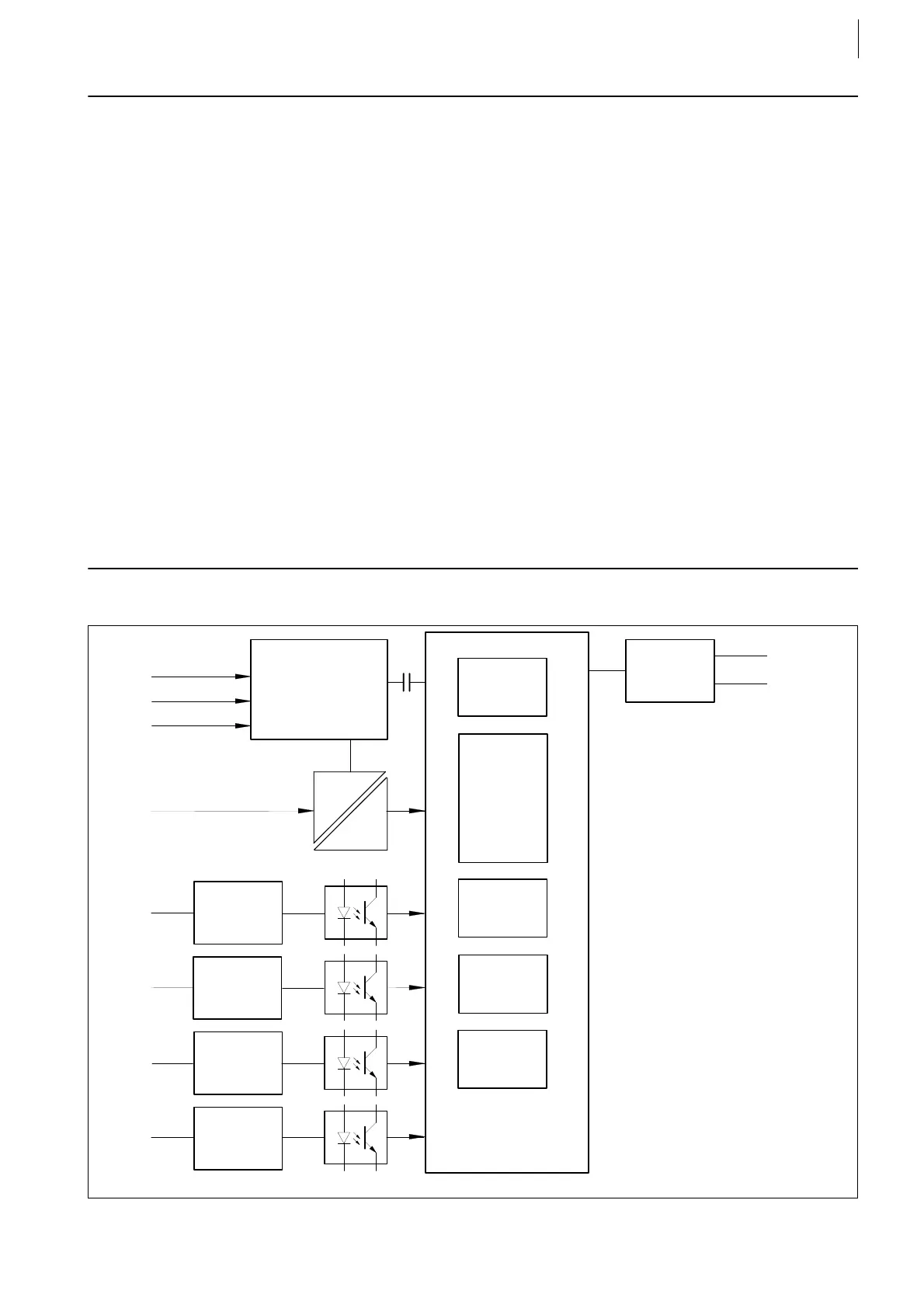
2.6 F-FEM-CNT Block Diagram
F-FEM-DAC for analog output
F-FEM-AIF for analog input
F-FEM-AIS for analog measurement with electrical isolation
F-FEM-AIN for analog measurement without electrical isolation
F-FEM-CON for controller
F-FEM-DIO for digital I/O
Fig. 4 F-FEM-CNT block diagram
IEEE1394 Interface
X21
X22
X11
Power
Supply
Add-On
Interface
X24
X25
to F-FEM-DIO
X17
X18
X29
X30
Signal
Conditioning
X23
Processor
Core
Signal
Conditioning
Signal
Conditioning
Signal
Conditioning
Program-
mable
Logic
Thermo-
meter etc.
Counter
1 ... 6
RAM
FLASH
VCXO
EEPROM
 Loading...

