Operation
46
F-FEM-CNT — User’s Guide
4.4.2
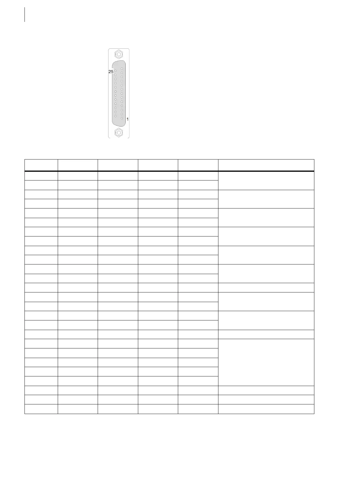
Sensor Inputs: X17, X18, X29, X30
If two sensors are connected at X17 or X18, two cables lead into the connector
housing.
Fig. 29 25-pin SUB-D for X17, X18, X29, X30
Pin X17 X18 X29 X30 Comment
5 IND1+ IND2+ IND3+ IND4+ Inductive pick-up
17 IND1- IND2- IND3- IND4-
7 + 5 V + 5 V + 5 V + 5 V Supply for incremental encoder
20 + 5 V + 5 V + 5 V + 5 V
6 U1_0+ U2_0+ U3_0+ U4_0+ Zero track
18 U1_0– U2_0– U3_0– U4_0–
8 U1_1+ U2_1+ U3_1+ U4_1+ Track A
21 U1_1– U2_1– U3_1– U4_1–
9 U1_2+ U2_2+ U3_2+ U4_2+ Track B
22 U1_2– U2_2– U3_2– U4_2–
10 DGND DGND DGND DGND Supply for incremental encoder
23 DGND DGND DGND DGND
13 + 24 V + 24 V + 24 V + 24 V (OUT for DI)
11 DI1 A DI2 A DI3 A DI4 A Track A
24 DI1 A DI2 A DI3 A DI4 A
12 DI1 B DI2 B DI3 B DI4 B Track B
25 DI1 B DI2 B DI3 B DI4 B
16 GND_24 GND_24 GND_24 GND_24
14 nc nc nc nc
nc = pin without internal connection
15 nc nc nc nc
2ncncncnc
3ncncncnc
4ncncncnc
1 Shielding Shielding Shielding Shielding
19 Shielding Shielding Shielding Shielding
Case Shielding Shielding Shielding Shielding
Tab. 7 Sensor inputs
 Loading...

