Installation
26
F-FEM-CNT — User’s Guide
3.3.3
Grounding and Shielding
3.3.3.1
Grounding
For grounding, the following must be considered:
Prevent dangerous contact voltage at electrically conductive parts.
Parasitic currents must be led back to their source of origin via the shortest
route possible.
This requires low grounding resistance and compliance with the high frequen-
cyrules regarding installation, wire types and contacting.
• Please regard the following points:
– The F-FEM-CNT is electrically isolated from the 24 V DC supply. For
safety purposes, the case is connected to the ground via a PE and via
the DIN rail (to avoid radio frequency interferences). The PE is carried
in the power supply cable.
– If several F-FEM clusters are connected with each other in a network,
every cluster should be grounded with low inductance to the ground of
its local signal source.
– If an IEEE1394 interface is used, ground wires must be used between
the individual F-FEM clusters as well as between the first cluster and
the host system (PUMA, test bed workstation). Potential equalization is
ensured by the PEs, which are carried in the supply lines. The ground
wires minimize the effects of the ground loop between the different
ground potentials of the network (please refer to Fig. 14 on page 28).
– To avoid ground loops completely, a fiber optic link can be used to con-
nect the clusters or to connect PUMA and the first cluster (please refer
to Fig. 15 on page 29). In this case, a compensatory current over the
ground wires and over the supply wire shielding is possible.
– If the ground of the engine in the test cell and of the host system have
to be separated (e.g. due to too great a distance or ground loops), the
F-FEM cluster which is assigned to the engine in the test cell should
have its own 24 V power supply. Then the shielding of the power
supply lines of the F-FEM cluster must be connected via a capacitor to
the same PE to which the 24 V power supply is connected. The ground
wire must then be clamped to the 0 V output of the 24 V power supply
(please see Fig. 16 on page 30).
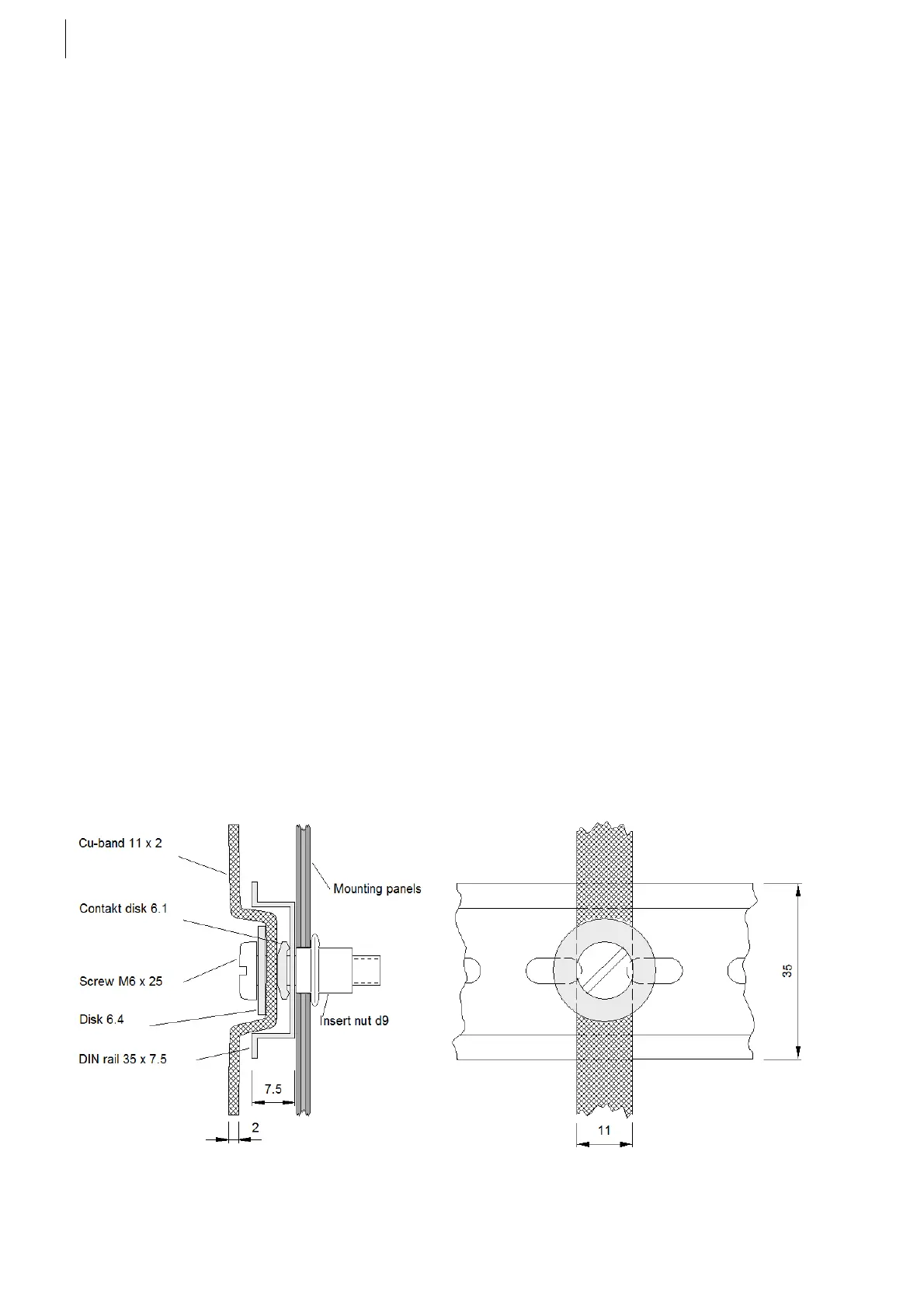
Fig. 12 Example: Mounting of ground braid at insert nut
 Loading...

