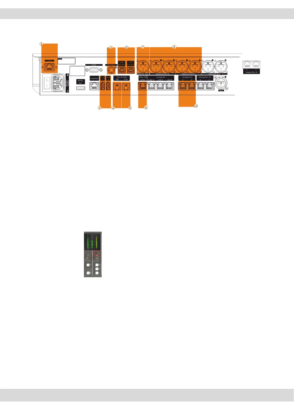
AOIP – LAN DANTE* – RJ45 (CAT 6 cable).
8 Stereo digital audio outputs over Ethernet. These
outputs are optional. if DANTE board was not
purchased when purchasing the device these outputs
are not enabled and do not work. Instead of these
outputs, USB AUDIO 1 and USB AUDIO 2 outputs will
be active.
The first DANTE-1 audio output over Ethernet could be
selected as 2 additional Telco N-1 Output (DANTE-
OUT-Out-L and DANTE-Out-1-R) of the additional
Telco4 (Dante-In-1-L) and Telco5 (Dante-In-1-R).
USB 3, USB 4 ports Type A to Export and Import the
mixer configurations.
Import LOGO
PHONES on female Jack 6,5 mm connector for the
audio monitoring with Control Room Headphones.
This connector works in parallel with the following
surface one:
SET connector on RJ11, to plug a POTS/PSTN
telephone device to speak with the caller before airing
him.
Telephone
Analog Telephone Line Input - RJ11 – for POTS/PSTN
interfacing. On this connector pass both input and
output signals.
USB AUDIO 1, USB AUDIO 2
2 Audio Card Stereo Output - USB-Type B - PC
Connections. If DANTE board was purchased these
ports will not be present and will be automatically
disabled. Playback Sample Rate to be set on the PC
Control Panel is 48000 Hz
DIGITAL OUT on XLR Male connector for the digital
AESEBU output audio signal.
ANALOG-OUT-1, ANALOG-OUT-2
2 Stereo Output transporting - XLR Male - Balanced
Audio Connection (23Ω) nominal (600Ω).
The ANALOG-OUT-1 is fixed on PGM BUS.
The ANALOG-OUT-2 usually is by default set for the
Control Room-SPEAKERS.
If needed ANALOG-OUT-2 could be set as 2 Telco N-
1 Outputs (ANALOG-OUT-2-L and ANALOG-OUT-2-R)
of the additional Telco2 and Telco 3.
Telco I/O GPIO – RJ45 (SFTP cable). The RJ45 cable
transports TELCO-Input and TELCO Output. Through
RJ45 is also carried 2 GPIO signals. 1 GPI to get the
incoming call signal by the flashing of the F1 button.
1 GPO to control the external hybrid device for hook
and drop purposes.
Pinout – in scheme
+188 – Oxy1000/Oxy2000-RJ45-Telco
ANALOG OUT 3, ANALOG OUT 4 - on RJ45 (SPTF
Cable) for the STUDIO HEADPHONES and 1 GPO
signal for ONAIR LIGHTS and TALKBOXES.Pinout - in
scheme
+190 - Oxy1000/Oxy2000RJ45-LineOut
NB:
- The audio signal of the logical PGM audio
BUS is automatically routed to the
ANALOG-OUT-1 phisical BUS.
- The audio signal of the PGM, SUB, AUX-1,
AUX-2, SPK-CR, HDP-CR, SPK-ST, HDP-ST
logical BUSS can be routed to the ANALOG-
OUT-2, ANALOG-OUT-3, ANALOG-OUT4
phisical audio BUSS.
- AUX1 and AUX2 logical BUSS are only
available on the OXYGEN REMOTER
controlling software and can be routed to
the ANALOG-OUT-2, ANALOGUE-OUT-3,
ANALOG.