AXIS 200
User’s Manual Section 2: Installing the AXIS 200
11
Stage 2. Identifying the Connectors and Indicators
Please read the following information to familiarize yourself with the
AXIS 200, making particular note of where the connectors and
indicators are located. This information provide a useful reference
when performing the remaining stages of the installation.
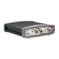
Connectors
Auxiliary I/O
Connector
A Mini-DIN 8-pole external connector for auxiliary connection to the
AXIS 200. The functionality of this connector is fully discussed in
Appendix E - The Auxiliary IO Port.
RS232 Serial
Connector
A 9 pin D-sub connector provides the physical RS232 serial interface
to a modem server within the AXIS 200. This connector is discussed
in detail in Appendix F - The RS232 Serial Port.
Ethernet 10baseT
Connector
10baseT (RJ-45) twisted pair Ethernet connector for connection to
the network.
Power Supply
Connector
Jack socket for connection of AXIS 200 power supply.
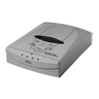
Network indicator
Power indicator
Rear view
Control button
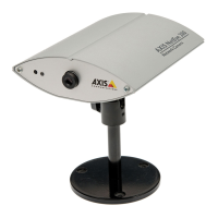
Front view
Ethernet 10baseT connector
RS232 serial connector
Power supply connector
Snapshot indicator
Auxiliary I/O connector
Camera lens
Serial number
(with rotational focus control)