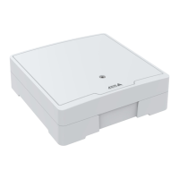
AXISA1001NetworkDoorController&AXISEntryManager
TechnicalSpecications
Function
Specications
PowerandEthernet
PoweroverEthernetIEEE802.3af/802.3atType1Class3
Maxloadonoutputs=7.5W
PowerLockConnector
4-pinterminalblockforpoweringoneortwolocks(DCoutput).Thelockconnectorcanalso
beusedtopowerexternaldevices.
Connectlocksandloadstothepinsaccordingtothehardwarepinchartgeneratedthrough
thehardwareconguration.
FunctionPinNotes
Specications
0VDC(-)
1,3
0VDC
0VDC,oating,or
12VDC
2,4
Forcontrollinguptotwo12Vlocks.Usethehardware
pinchart.SeeConguretheHardware,onpage11.
12VDC
Maxtotalload=500mA
Power&RelayConnector
6-pinterminalblockwithbuilt-inrelayfor:
•Externaldevices
•Auxiliarypower(DCoutput)
•0VDC(-)
Connectlocksandloadstothepinsaccordingtothehardwarepinchartgeneratedthrough
thehardwareconguration.
FunctionPinNotes
Specications
0VDC(-)
1,4
0VDC
Relay
2–3
Forconnectingrelaydevices.Usethehardwarepin
chart.SeeConguretheHardware,onpage11.
Thetworelaypinsaregalvanicallyseparatedfromthe
restofthecircuitry.
Maxcurrent=700mA
Maxvoltage=+30VDC
12VDC
5
Forpoweringauxiliaryequipment.
Note:Thispincanonlybeusedaspowerout.
Maxvoltage=+12VDC
Maxload=500mA
TamperingAlarmPinHeader
Two2-pinheadersforbypassing:
•Backtamperingalarm(TB)
•Fronttamperingalarm(TF)
FunctionPinNotes
Backtamperingalarm
1–2
Fronttamperingalarm
1–2
Tobypassthefrontandbacktamperingalarmsimultaneously,connectjumpers
betweenTB1,TB2andTF1,TF2respectively.
51