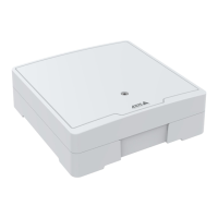
AXISA1001NetworkDoorController&AXISEntryManager
HardwareOverview
GreenSteadywhennotenergized.
Red
Steadywhenenergized.
Lock
UnlitFloating.
Note
•TheStatusLEDcanbeconguredtoashwhileaneventisactive.
•TheStatusLEDcanbeconguredtoashforidentifyingtheunit.GotoSetup>AdditionalControllerConguration>
SystemOptions>Maintenance.
ConnectorsandButtons
Fortechnicalspecications,seepage45.
I/OInterface
ReaderDataConnector
Two6-pinterminalblockssupportingRS485andWiegandprotocolsforcommunicationwiththereader.
ReaderI/OConnector
Two6-pinterminalblocksforreaderinputandoutput.Inadditiontothe0VDCreferencepointandpower(DCoutput),the
readerI/Oconnectorprovidestheinterfaceto:
•Digitalinput–Forconnecting,forexample,readertamperingalarms.
•Digitaloutput–Forconnecting,forexample,readerbeepersandreaderLEDs.
DoorConnector
Two4-pinterminalblocksforconnectingdoormonitoringdevicesandrequesttoexit(REX)devices
AuxiliaryConnector
4-pincongurableI/Oterminalblock.Usewithexternaldevices,incombinationwith,forexampletamperingalarms,eventtriggering
andalarmnotications.Inadditiontothe0VDCreferencepointandpower(DCoutput),theauxiliaryconnectorprovidesthe
interfaceto:
•Digitalinput–Analarminputforconnectingdevicesthatcantogglebetweenanopenandclosedcircuit,forexamplePIR
sensorsorglassbreakdetectors.
•Digitaloutput–Forconnectingexternaldevicessuchasburglaralarms,sirensorlights.Connecteddevicescanbe
activatedbytheVAPIX®applicationprogramminginterfaceorbyanactionrule.
ExternalPowerInputs
NOTICE NOTICE
NOTICE
Theproductshallbeconnectedusingashieldednetworkcable(STP).Allcablesconnectingtheproducttothenetworkshall
beintendedfortheirspecicuse.Makesurethatthenetworkdevicesareinstalledinaccordancewiththemanufacturer’s
instructions.Forinformationaboutregulatoryrequirements,seeElectromagneticCompatibility(EMC),onpage2.
PowerConnector
2-pinterminalblockforDCpowerinput.UseaSafetyExtraLowVoltage(SELV)compliantlimitedpowersource(LPS)witheither
aratedoutputpowerlimitedto≤100Woraratedoutputcurrentlimitedto≤5A.
NetworkConnector
RJ45Ethernetconnector.SupportsPoweroverEthernet(PoE).
PowerOutputs
PowerLockConnector
4-pinterminalblockforconnectingoneortwolocks.Thelockconnectorcanalsobeusedtopowerexternaldevices.
8