AXIS P33/P33-V Network Camera Series Installation Guide Page 19
ENGLISH
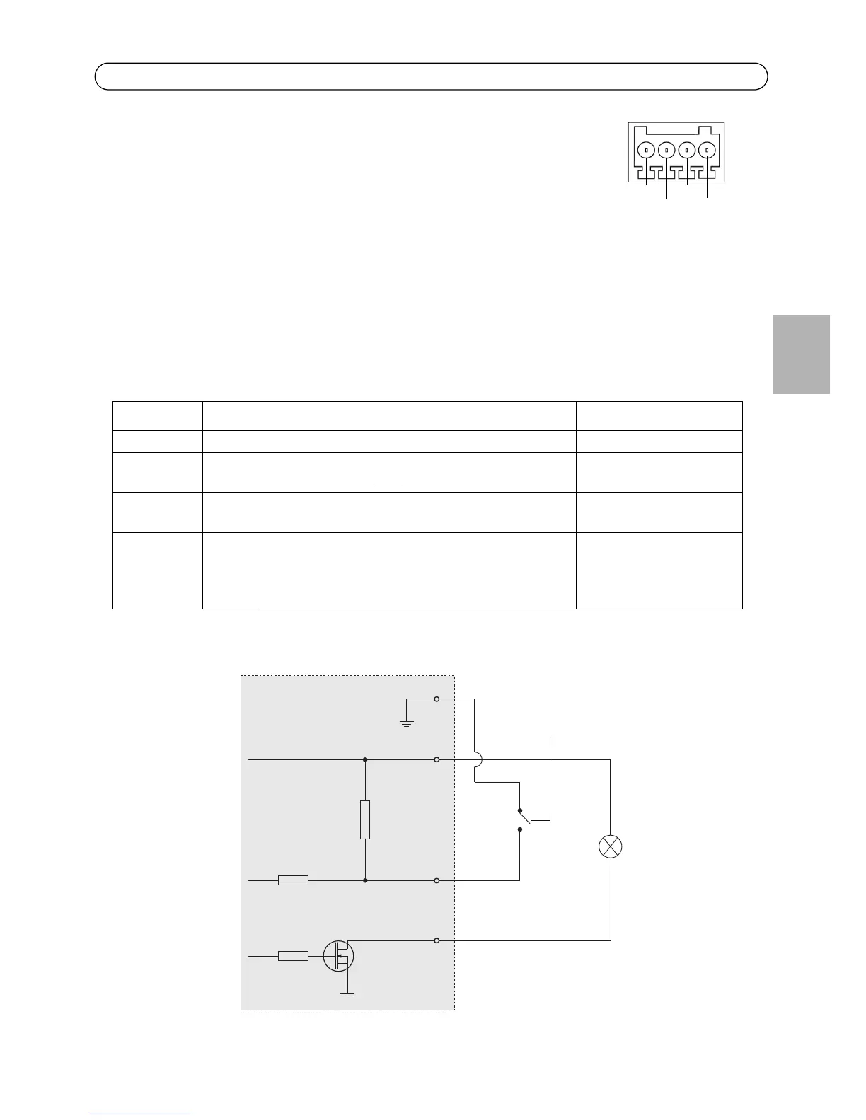
I/O terminal connector - Used in applications for e.g. motion detection,
event triggering, time lapse recording and alarm notifications. In addition to
an auxiliary power and a GND pin, it provides the interface to:
• 1 transistor output - For connecting external devices such as
relays and LEDs. Connected devices can be activated by the
VAPIX® Application Programming Interface (API), by the output buttons on the Live
View page or by an Action Rule. The output will show as active (shown under System
Options > Ports & Devices) if the alarm device isactivated.
• 1 digital input - An alarm input for connecting devices that can toggle between an
open and closed circuit, for example: PIRs, door/window contacts, and glass break
detectors. When a signal is received the state changes and the input becomes active
(shown under System Options > Ports & Devices).
The following connection diagram gives an example of how to connect an auxiliary device to the
Fixed Dome Network Camera.
Function Pin Notes Specifications
GND 1 Ground
3.3V DC
Power
2 Can be used to power auxiliary equipment.
Note: This pin can only
be used as power out.
Max. load = 50mA
Digital
Input
3 Connect to GND to activate, or leave floating (or
unconnected) to deactivate.
Min. input= - 40V DC
Max. input= + 40V DC
Digital
Output
4 Uses an open-drain NFET transistor with the source
connected to GND. If used with an external relay, a
diode must be connected in parallel with the load,
for protection against voltage transients.
Max. load = 100mA
Max voltage = + 40V DC