AXIS Q19 Series Installation Guide Page 9
ENGLISH
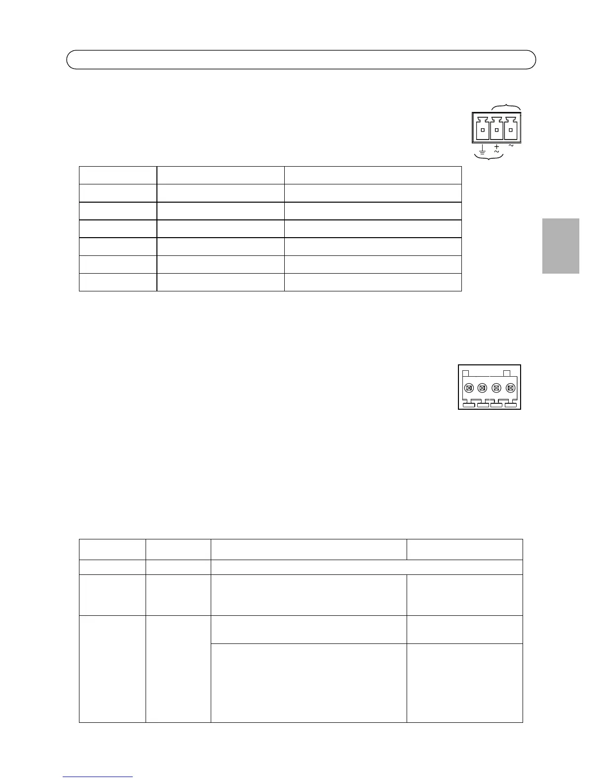
Power - 3-pin terminal block used for power input. Use a limited power source, such
as a mains adaptor, which rated power output does not exceed either 100 W or 5 A.
If the Axis product's input voltage is less than 20 V, the current from the mains
adaptor shall still be limited to 5 A. If the mains adaptor has a higher output
voltage than 20 V, its power output shall still be limited to 100 W.
I/O terminal connector - Used in applications for e.g. motion detection, event
triggering, time lapse recording and alarm notifications. In addition to an
auxiliary power and a GND pin, the network camera has 2 pins that can be
configured as either input or output. These pins provide the interface to:
• Transistor output - For connecting external devices such as relays and
LEDs. Connected devices can be activated by AXIS VAPIX API, output
buttons on the Live View page or by an Event Type. The output will show as active (shown
under Events > Port Status) if the alarm device is activated.
• Digital input - An alarm input for connecting devices that can toggle between an open and
closed circuit, for example: PIRs, door/window contacts, glass break detectors, etc. When a
signal is received the state changes and the input becomes active (shown under
Events > Port Status.)
Model Power requirements DC Power requirements AC
AXIS Q1910 8-20 V DC, max 10 W 20-24 V AC, 50/60Hz, max 15 VA
AXIS Q1910-E 8-20 V DC, max 13 W 20-24 V AC, 50/60Hz, max 18 VA
AXIS Q1921 8-20 V DC, max 7 W 20-24 V AC, 50/60Hz, max 13 VA
AXIS Q1921-E 8-20 V DC, max 12 W 20-24 V AC, 50/60Hz, max 18 VA
AXIS Q1922 8-20 V DC, max 9 W 20-24 V AC, 50/60Hz, max 14 VA
AXIS Q1922-E 8-20 V DC, max 13 W 20-24 V AC, 50/60Hz, max 20 VA
!
CAUTION! - Incorrect connection of the wires could cause damage to the camera.
Function Pin number Notes Specifications
GND 1 Ground
3.3 V DC
Power
2 Can be used to power auxiliary equipment.
Note:
This pin can only be used as power out.
Max load = 250 mA
Configurable
(Input or
Output)
3 - 4 Digital input - Connect to GND to activate, or
leave floating (or unconnected) to deactivate.
0 to +40 V DC
Digital output - Internal connection to
ground when activated, floating
(unconnected) when deactivated. If used
with an inductive load, e.g. a relay, a diode
must be connected in parallel with the load,
for protection against voltage transients.
Max load = 100 mA
Max voltage = +40 V DC
 Loading...