SPECIFICATIONS
DEFINITIONS
22
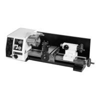
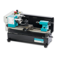
Axminster No 600857
Power Supply 230V a.c. 50 Hz.
Motor 220V d.c. 150W
Quill Travel 30mm
Spindle Speeds Low Gear 100-1000rpm (variable) High Gear 100-2000 rpm (variable)
Reversing Method Electrical
Quill Mandrel Taper No. 2 MT
Draw Bar Thread M10
Drilling Capacity 10mm
End Mill Capacity 10mm
Face Mill Capacity 20mm
Weight 25 Kg
ʻXʼ Axis. This is the axis described by the work table as it is moved side to side.
Normally, movement that moves the tool to the right in the workpiece is
referred to as +ve ʻXʼ, and movement that moves the tool to the left in the
workpiece is referred to as –ve ʻXʼ. Where the initial position of the tooling
and the worktable is designated 0,0. (Horizontal plane only).
ʻYʼ Axis. This is the axis described by the work table as it is moved from front to
back. (Traverse) Normally movement that moves the tool to the front in
the workpiece is referred to as-ve ʻYʼ, and movement that moves the tool
to the rear in the workpiece is referred to as+ve ʻYʼ. Where the initial
position of the tooling and the worktable is designated 0,0.(Horizontal
plane only).
ʻZʼ Axis This is the axis described by the worktable in the vertical plane.
(Not possible with this machine). However, to establish a point in space,
the co-ordinates can be transferred to the ʻtipʼ of the tooling, whereby, if
we assume that the tool and the worktable in their initial positions, where
designated 0,0,0, (Horizontal and vertical planes) any point above the tool
tip is referred to as +ve ʻZʼ, and any point below the tool tip is referred to
as -ve ʻZʼ