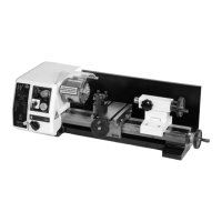
PARTS IDENTIFICATION AND DESCRIPTION
Gear change The gear change knob allows the selection of the high or low ratio
knob of the gear train. The speed of the spindle is then governed by the
speed control on the motor panel. (You may have to ʻjoggleʼ the
chuck/tool to aid the meshing action).
Motor A 220V d.c. motor rated at 150W.
Feed Handle Lever handle that is used to drive the quill (and hence the chuck or
the tool) up and down. The boss of the handle is fitted to the end
of a ʻsplinedʼ gear shaft. This ʻsplinedʼ gear is, in turn, engaged in
the rack cut into the quill body. There is a counter balance spring in
the arbor and sleeve assembly, giving a more controlled ʻfeelʼ
during drilling operations. It also retracts the quill when drilling is
completed.
Fine feed The fine feed assembly floats around the splined gear shaft that
assembly drives the quill up and down. When the action of the fine feed
mechanism is required; pulling out ʻengageʼ knob of the fine feed
control meshes the gearing (you may have to ʻjoggleʼ the feed
handle to aid the meshing action) between the splined shaft and
the fine feed control shaft; this enables the spindle to be driven by
the fine feed control wheel with greater precision. Behind the boss
of the fine feed control wheel handle is a graduated ring (thimble)
so that the movement of the quill can be measured. The thimble is
held to the drive shaft by friction, and can be pre-positioned to
establish a predetermined start or stop dimension.
Motor control Power On LED
panel Green LED that indicates that power is available to the motor. i.e.
mains is applied, fuse is intact and the Emergency stop switch is
not activated.
Fault LED
(marked UNNORMAL)
Amber LED that indicates that there is a fault or an incorrect
control sequence. i.e. the chuck guard interlock has been activated
or the speed control is activated without forward or reverse direction
being selected. The Motor will not run if the fault LED is illuminated. If
the safety interlock is activated, the safety interlock will remain in force
until the interlock is reset and the start sequence re-initiated.
Fuse Cap
Access cap for the 20mm fuse cartridge (1 Amp 250V) Speed Control
Knob Round raised ridge knob connected to the circuit that controls the
spindle speed (100-1000 rpm or 100-2000 depending upon the
gearbox selection).
Forward /Off/Reverse Switch
Three position switch that controls the direction of rotation of the
spindle. Forward indicates that the spindle is turning clockwise (looking
down from above, reverse, the spindle is turning anticlockwise. The
centre OFF position inhibits the spindle from turning in either direction,
under motor drive.
28