Tutorials • 19
Chapter 3
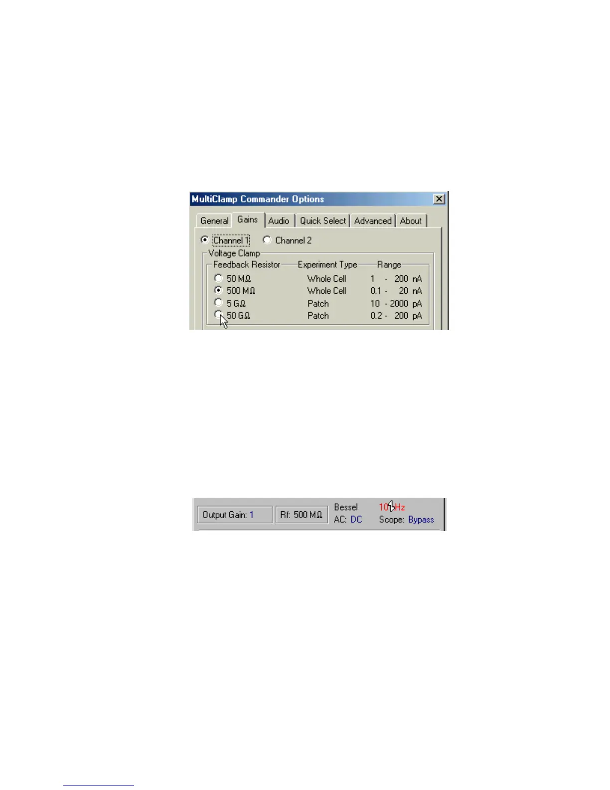
This opens the Options panel. Select the Gains tab. You will note that the default
Feedback Resistor under Channel 1 Voltage Clamp is 500 MΩ. Increasing the size
of the feedback resistor, which is located in the headstage, increases the gain of the
headstage. As a rule of thumb, the larger the value of the feedback resistor, the
smaller the noise of the headstage but the smaller the range of the output. For this
reason, larger feedback resistors are usually selected for patch recording, where
low noise is more important than range. (Note the information provided under
Experiment Type and Range in the Gains panel.)
Figure 2.11
Select 50 GΩ feedback resistor and then close this panel.
4. Note that the noise trace on the oscilloscope is now about 150 mV
p-p
. However,
the Scaled Output gain shown under Output Signals is now 50 V/nA, so the noise
is 3 pA
p-p
, a 3-fold reduction compared with before. This is still quite noisy for
recording single-channel currents of a few picoamps. To clearly see small
currents, it is necessary to filter the Scaled Output.
5. Locate the Output Signals section in the main window of the MultiClamp
Commander and position the mouse cursor over 10 kHz opposite Bessel. Using
the glider control (see Chapter 2) explore the effect of filtering the Scaled Output.
Figure 2.12