4 • Installation and Basic Operation
MultiClamp 700A Theory and Operation, Copyright 2000, 2001 Axon Instruments, Inc.
available). In order to use on-line Help, the PC should have Internet access and a
web browser with JavaScript (Internet Explorer v. 4 or later, or equivalent).
Installing Hardware
1. Connect one end of the RS232 “Null Modem” cable to the RS232 IN connector on
the MultiClamp 700A main unit and the other end to a free serial port on your PC.
Use the DB9 to DB25 adapter if the computer port is a 9-pin type.
2. Connect the CV-7A headstages to HEADSTAGE 1 and HEADSTAGE 2 rear
panel connectors.
3. Power up the MultiClamp 700A. The front panel POWER light (light emitting
diode or LED) should illuminate, as well as either the VOLTAGE CLAMP or
CURRENT CLAMP LED for each channel.
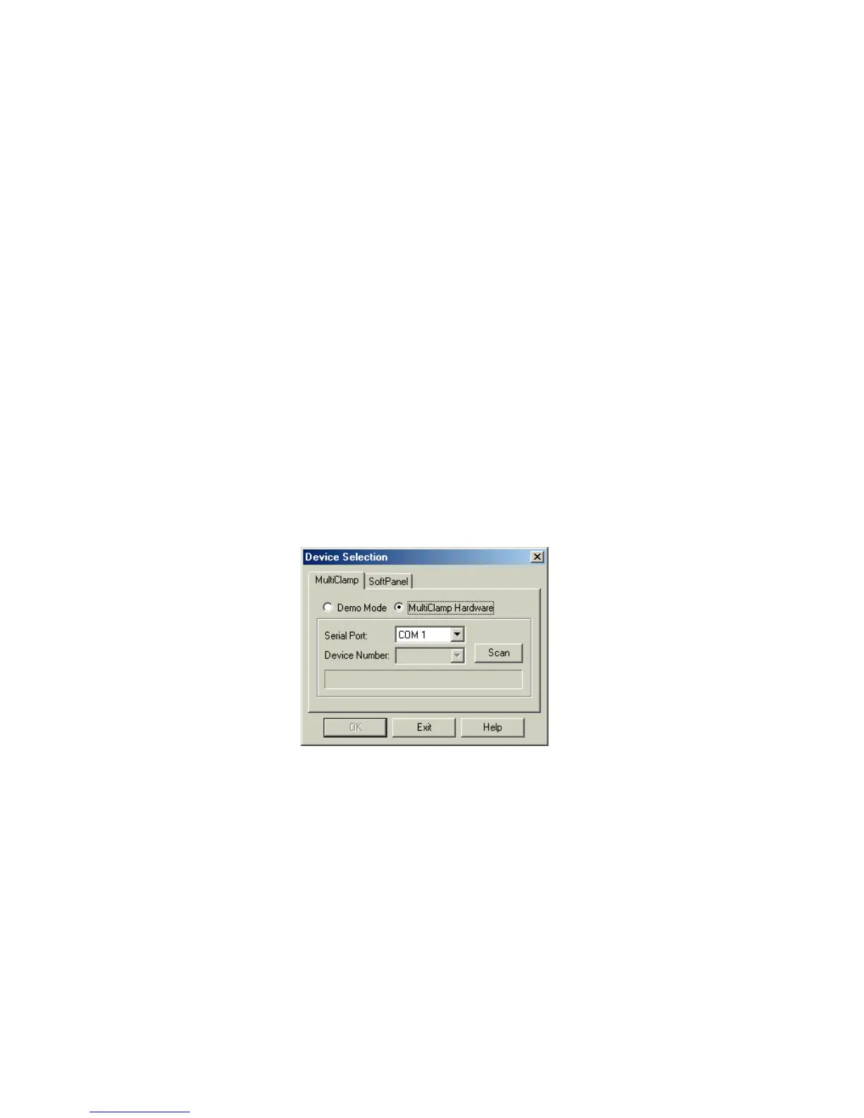
Installing the MultiClamp Commander
1. Run the MultiClamp Commander installer. This will install all necessary files into
a directory (‘Axon\MultiClamp1’) on your hard drive and generate a shortcut on
your desktop.
2. Run MULTICLAMP.EXE by double clicking on the MultiClamp icon on the
desktop. The first time the program is run the following panel will appear:
Figure 1.1