6 • Installation and Basic Operation
MultiClamp 700A Theory and Operation, Copyright 2000, 2001 Axon Instruments, Inc.
Functional Checkout
The purpose of this section is to quickly check the correct operation of the MultiClamp
700A and to briefly describe the basic controls of the MultiClamp Commander. With
this information and the On-line Help, the experienced researcher should be able to
work comfortably with the features of the amplifier. However, we recommended that
the Tutorials (see page 13) and Calibration procedure (see page 10) be followed for
maximum benefit.
Communication with the MultiClamp 700A
1. Check that the STATUS LED on the front of the MultiClamp 700A is flashing.
This indicates that the MultiClamp Commander is polling the MultiClamp 700A,
updating its meter displays.
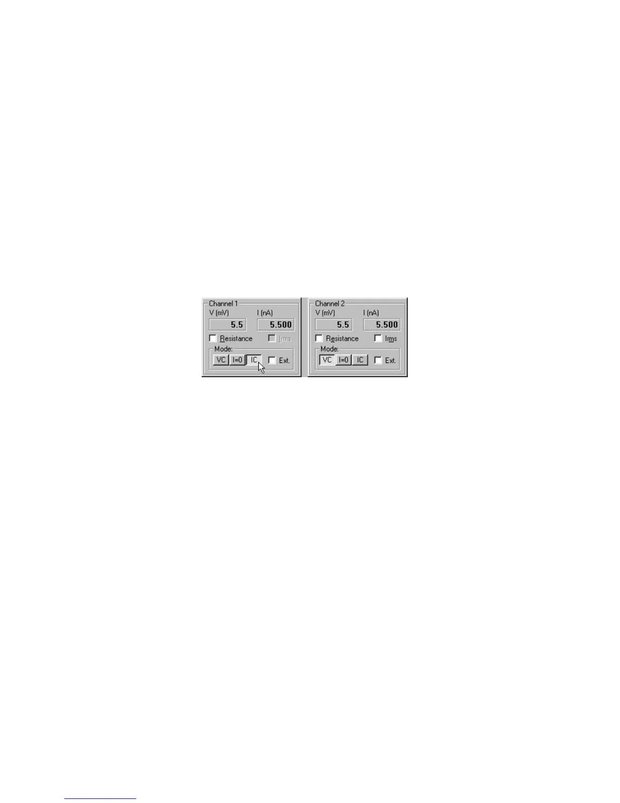
2. Toggle the Channel 1 Mode and Channel 2 Mode buttons, switching repeatedly
between Voltage Clamp (VC) and Current Clamp (I=0, IC) modes:
Figure 1.3
The tabs immediately below the mode switches will change appropriately. Also, the
VOLTAGE CLAMP and CURRENT CLAMP indicator lights on the front panel of
the MultiClamp 700A should switch correctly, confirming that the amplifier is
changing mode.
Setting Parameters in the MultiClamp Commander
Many parameter fields in the MultiClamp Commander can be set in three different
ways. To demonstrate this, press the V-Clamp 1 tab and try the following.