10 • Installation and Basic Operation
MultiClamp 700A Theory and Operation, Copyright 2000, 2001 Axon Instruments, Inc.
5. Repeat the Irms noise measure for each Feedback Resistor selected from the
MultiClamp Commander Options menu.
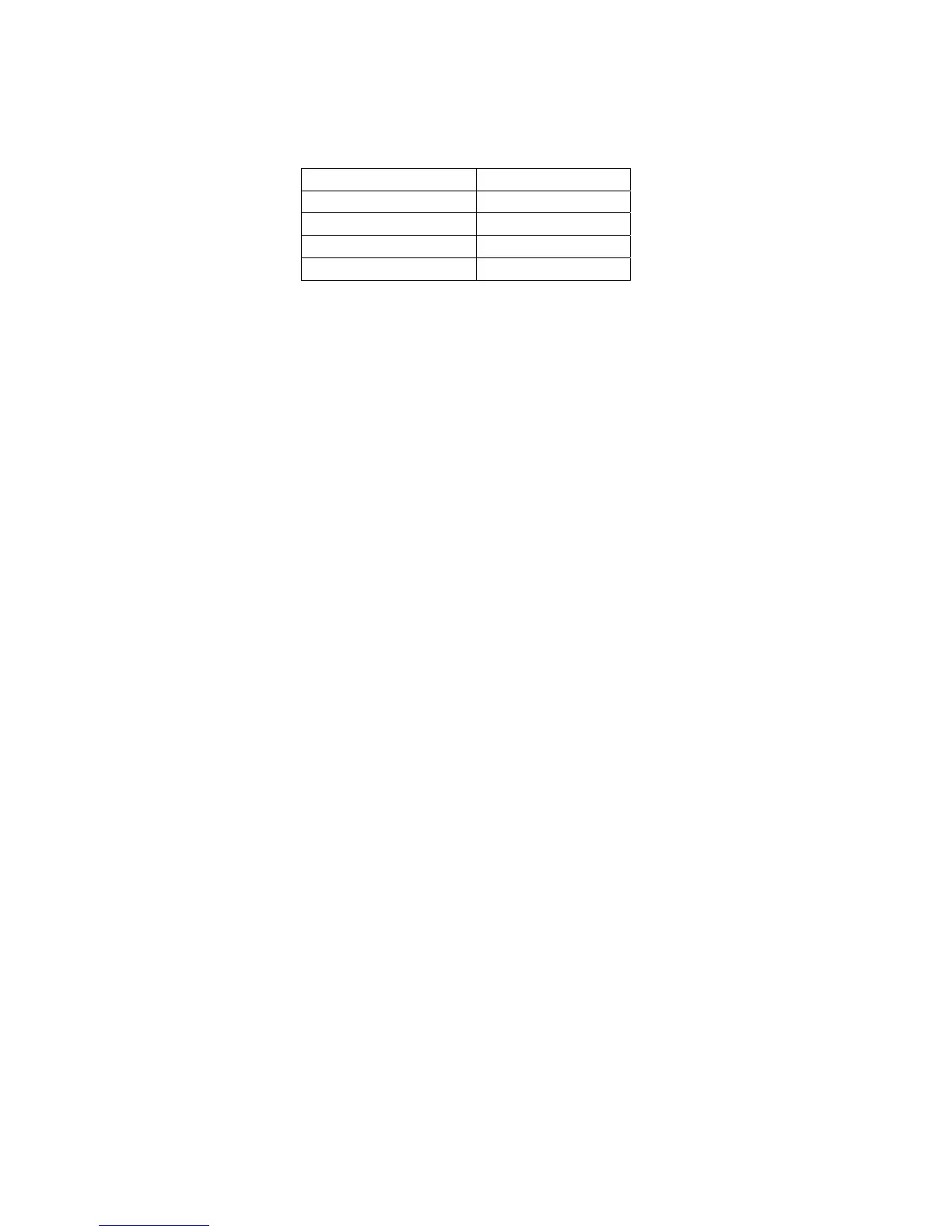
Feedback Resistor Noise*
50 MΩ 2.0 pA rms
500 MΩ 0.8 pA rms
5 GΩ 0.5 pA rms
50 GΩ 0.15 pA rms
6. If your MultiClamp has more than one CV-7A headstage, repeat steps 1-5 for
the second headstage.
Calibration
• Procedure for checking the calibration of the MultiClamp 700A.
The steps below provide a quick check of the calibration of the MultiClamp 700A. It
is assumed that appropriate shielding (as described in “Test the Noise”, above) will be
used during these tests.
1. Connect an oscilloscope to the front panel SCALED OUTPUT or SCOPE
OUTPUT BNC.
2. Synchronize the oscilloscope by connecting to the rear panel SYNC OUTPUT
BNC.
Press the “Reset to Program Defaults” button on the MultiClamp Commander to
standardize the MultiClamp 700A.
50 G Range
1. Press the “Options” button, choose the Gains tab, and select the 50G
feedback resistor in the Voltage Clamp pane. Return to the main
MultiClamp Commander window.
2. Plug the PATCH connector of the PATCH-1U model cell into the CV-7A
headstage.