22 • Tutorials
MultiClamp 700A Theory and Operation, Copyright 2000, 2001 Axon Instruments, Inc.
experiments with real cells you may need to make manual fine adjustments for
optimal cancellation.
10. Sometimes an additional, slower capacitance transient is visible after canceling the
fast transient in the PATCH configuration (not to be confused with the very slow
transient that appears in the CELL configuration, discussed in Tutorial 4.) This
can be compensated using the Cp Slow controls. The PATCH setting on the model
cell has only a very minor slower transient.
11. Now that the capacitance transients are compensated, it will be possible to increase
the amplitude of the Seal Test pulse without overloading the MultiClamp 700A.
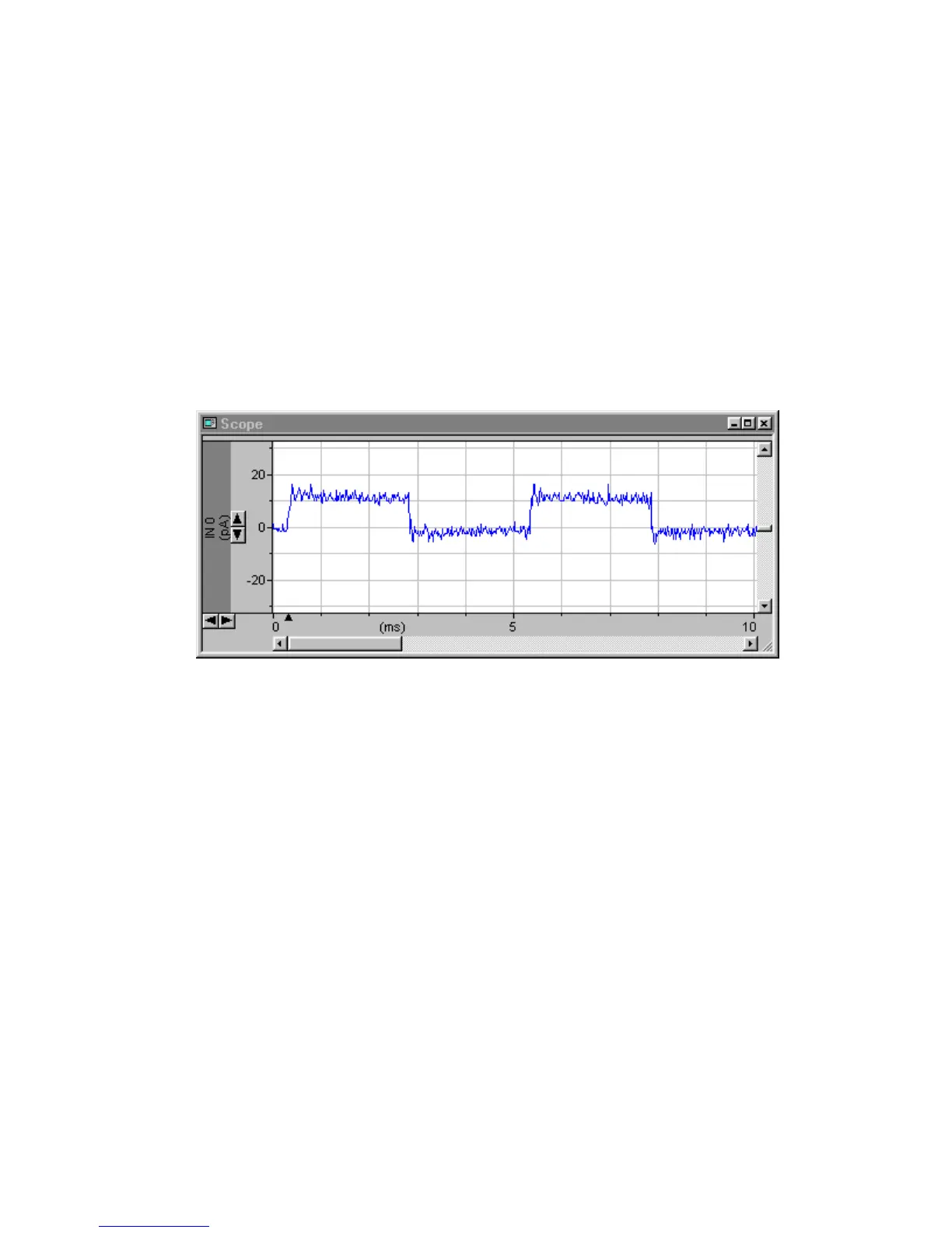
Set the Seal Test amplitude to 100 mV by placing the cursor over the display
(10 mV), double clicking and typing 100 <Enter>. Clear steps should now be
visible on the oscilloscope, with amplitudes of about 5 mV.
Figure 2.15
With the “Scaled Output: Membrane Current” gain set at 0.5 V/nA, this is
equivalent to 10 pA. Hence the resistance of the model patch is calculated from
Ohm’s Law to be R = V/I = 100 mV/10 pA = 10 GΩ. Alternatively, check the
Resistance checkbox under the Channel 1 meters.