82 • Reference Section
MultiClamp 700A Theory and Operation, Copyright 2000, 2001 Axon Instruments, Inc.
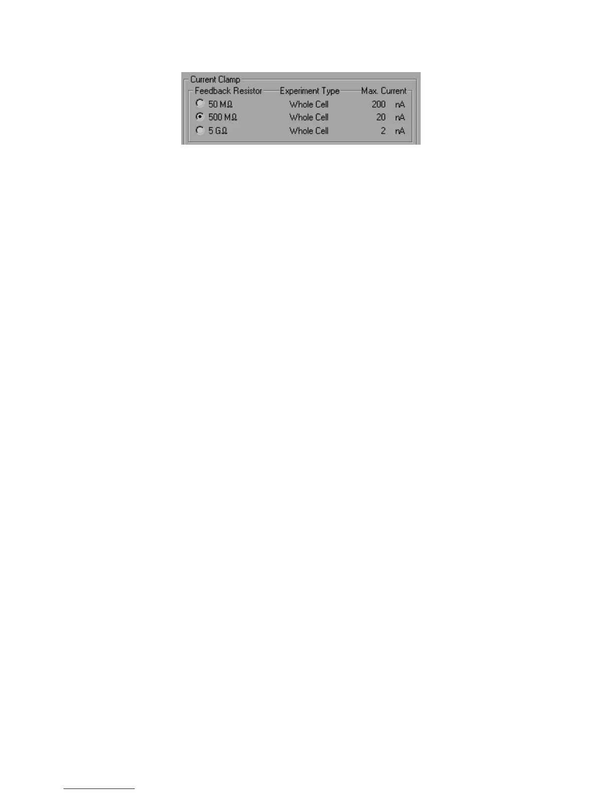
Figure 4.9
As a rule of thumb, it is best to use the largest possible value of R
f
without risk of
saturation. Be aware that incompletely compensated capacitance transients, which are
brief and often hard to see, may saturate before ionic currents. The OVERLOAD LED
on the front panel of the MultiClamp 700A will assist you in judging when saturation
has occurred.
Note that R
f
can be changed safely “on the fly” with a cell or patch at the end of the
electrode. Under some conditions a small switching transient is generated at the input
of the headstage, and the cell sees this transient. However, after extensive tests on
many types of cells in all recording configurations, we have concluded that these
switching transients are too small to cause any damage to the cell membrane.
I-Clamp Mode
In I-Clamp mode, R
f
determines the maximum amount of current that can be injected
into the cell without saturating the headstage circuitry. To enable optimal
neutralization of input capacitance, R
f
values should be selected to match the resistive
load of the cell. If possible, the load should be in the range R
f
/10 to R
f
x 10. For
example, for a typical hippocampal pyramidal cell with an input resistance of 150 M,
R R
f
= 50 M is suitable.
Note that changing R
f
in I-Clamp mode changes the External Command Sensitivity for
I-Clamp.